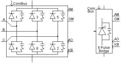
This component is a compact representation of a DC converter, which includes a built in 6-pulse Graetz converter bridge (can be inverter or rectifier), an internal Phase Locked Oscillator (PLO), firing and valve blocking controls and firing angle (a)/extinction angle (g) measurements. It also includes built in RC snubber circuits for each thyristor.
The general idea here is to eliminate the complex and tedious process of building a thyristor bridge, putting together controls, and coordinating the valve firing pulses involved in modeling an HVDC converter.
The 6 Pulse Bridge possesses the following external inputs and outputs:
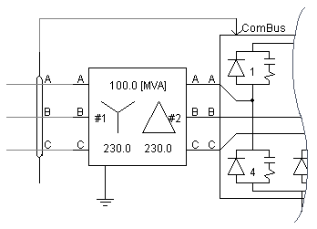
ComBus: Input signal to the internal Phase Locked Oscillator. This input is connected to the commutation bus though the Node Loop component as shown below:
AO: Input alpha order (firing angle) for the converter.
KB: Input block/deblock control signal. See Firing and Blocking Control for more details.
AM: Measured alpha (firing angle) output [rad].
GM: Measured gamma (extinction angle) output [rad].
More: |
Internal Phase Locked Oscillator (PLO) Choosing a Converter Transformer |
Name for Identification |
Text |
Optional text parameter for identification of the component. |
||
Thyristor Direction |
|
Choice |
|
Select Up or Down. Up signifies rectifier operation, whereas Down signifies inverter operation |
|
|
|
|
|
Firing Order Input |
|
Choice |
|
Select Angle in Radians, Array of 6 Pulses, 6 Pulses + 6 Interp. times or Angle in Degrees. This input configures the external alpha order input (AO) depending on how the bridge is to be controlled. See Firing and Blocking Control and Setting Up Firing Control for more details |
|
|
|
|
|
Use Snubber Circuit |
|
Choice |
|
Select Yes or No. See Snubber Circuit for more details |
|
|
|
|
|
Transformer Phase Shift |
|
REAL |
Constant |
Enter a transformer phase shift between -180° and 180° degrees [deg].
If the transformer valve side is lagging, then the phase shift should be entered as a negative value. For example, a Yd1 transformer configuration corresponds to -30°. |
|
|
|
|
|
Unblock Time |
|
REAL |
Constant |
The valve group will be locked until this time has passed. |
|
|
|
|
|
Graphics Display |
|
Choice |
|
Select 3 phase view, or Single line view |
Rated Frequency |
|
REAL |
Constant |
The system rated frequency [Hz] |
|
|
|
|
|
PLO Proportional Gain |
|
REAL |
Constant |
The proportional gain constant GP for the Internal Phase Locked Oscillator (PLO) |
|
|
|
|
|
PLO Integral Gain |
|
REAL |
Constant |
The integral gain constant GI for the Internal Phase Locked Oscillator (PLO) |
|
|
|
|
|
PLO Reference Voltage |
|
Choice |
|
Select Bus Voltage, Bus Voltage, Zero Sequence Removed, Star Source Voltage or Delta Source Voltage. This input adds a phase shift directly to the PLO output in order to account for the converter transformer configuration. The phase shift angles are summarized as follows:
See Choosing a Converter Transformer for more details |
Thyristor ON Resistance |
|
REAL |
Constant |
Resistance of all thyristors when in the ON state (conducting) [W] |
|
|
|
|
|
Thyristor OFF Resistance |
|
REAL |
Constant |
Resistance of all thyristors when in the OFF state [W] |
|
|
|
|
|
Forward Voltage Drop |
|
REAL |
Constant |
Forward voltage drop for all thyristors. This input may be 0 [kV] |
|
|
|
|
|
Forward Breakover Voltage |
|
REAL |
Constant |
Forward break-over voltage for all thyristors. Thyristors will be forced into conduction if this voltage is exceeded (with or without a gate pulse) [kV] |
|
|
|
|
|
Protected Against Forward Breakover |
|
Choice |
|
Select Yes or No.
If Yes is selected, the valve group will send a firing pulse just before the Forward Breakover Voltage is exceeded, avoiding permanent failure to the thyristor. |
|
|
|
|
|
Reverse Withstand Voltage |
|
Choice |
|
Select Same As Forward Breakover Voltage or Specify. |
|
|
|
|
|
Reverse Withstand Voltage |
|
REAL |
Constant |
Enter the reverse withstand voltage [kV]. This input is enabled only if Reverse Withstand Voltage | Specify is selected. |
|
|
|
|
|
Minimum Extinction Time |
|
REAL |
Constant |
Minimum extinction time for all thyristors. Thyristors will re-fire if the voltage exceeds Forward Voltage Drop within the this time since last turn off [ms] |
|
|
|
|
|
Snubber Capacitance |
|
REAL |
Constant |
Enter a value for snubber capacitance. See Snubber Circuit for more details [mF] |
|
|
|
|
|
Snubber Resistance |
|
REAL |
Constant |
Enter a value for snubber resistance. See Snubber Circuit for more details [W] |
Internal OutputsInternal Outputs
NOTE: If no name is specified, these output signals will not be monitored.
Firing Pulse Array(6) Name |
|
REAL |
Output |
Name for the 6-element array of firing pulses. Array number corresponds with valve number |
|
|
|
|
|
Snubber Circuit Current Array(6) Name |
|
REAL |
Output |
Name for the 6-element array of snubber circuit currents. Array number corresponds with valve number [kA] |
|
|
|
|
|
Valve Voltages Array(6) Name |
|
REAL |
Output |
Name for the 6-element array of valve voltages. Array number corresponds with valve number [kV] |
|
|
|
|
|
Valve Current Array(6) Name |
|
REAL |
Output |
Name for the 6-element array of valve currents. Array number corresponds with valve number [kA] |