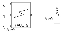
This component is used for generating faults on a three phase AC circuit. Line-to-line as well as line-to-neutral faults are available and fault current variable names can be specified in each phase and monitored via output channels if desired. An external connection is supplied to the component so that the user may connect any type of external fault circuit directly to the fault common point.
The Three-Phase Fault is controlled through an input signal, where the fault logic is:
0 = Cleared
1 = Faulted
The type of fault can be configured internally, or through the convenient use of an on-line dial control as shown below:
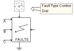
The following is a list of input control dial values that correspond to specific fault types:
0 = No Fault
1 = Phase A to Ground
2 = Phase B to Ground
3 = Phase C to Ground
4 = Phase AB to Ground
5 = Phase AC to Ground
6 = Phase BC to Ground
7 = Phase ABC to Ground
8 = Phase AB
9 = Phase AC
10 = Phase BC
11 = Phase ABC
The fault control signal can be configured automatically by using the Timed Fault Logic component, or the Sequencer components. The fault may also be controlled manually through the use of on-line controls, or through a more elaborate control scheme.
More: |
Fault Type Control |
|
Choice |
|
Select Internal or External |
|
|
|
|
|
Clear Possible if Current Flowing? |
|
Choice |
|
Select Yes or No.
If No is selected, the fault will wait for the next current zero following the clear signal, before clearing the fault |
|
|
|
|
|
Is the Neutral Grounded? |
|
Choice |
|
Select Yes or No. Select Yes to automatically ground the fault path |
|
|
|
|
|
Graphics Display |
|
Choice |
|
Select 3-Phase View or Single Line View |
|
|
|
|
|
Current Chopping Limit |
|
REAL |
Constant |
If Clearing Possible at Any Current? | No is selected, the fault will not clear until the absolute value of the fault current is less than this limit [kA]. |
Fault ResistancesFault Resistances
Fault ON Resistance |
|
REAL |
Variable |
Enter a small value to represent the branch resistance during a faulted state. This value is usually in the order of 0.01 (default), and is internally limited so that it is always less than 1% of the Fault OFF Resistance [W].
NOTE: Although this parameter is configured to take a variable signal, it cannot be changed dynamically. The value of the signal at first time step is taken as the ON resistance, independent of the project startup method (i.e. from Data File or Snapshot File). This allows the ability to change the ON resistance when the project is started from a snapshot, without invalidating the snapshot file.
NOTE: If this value is less than the ideal branch threshold, the fault will be modeled as an ideal branch while in the faulted state. |
|
|
|
|
|
Fault OFF Resistance |
|
REAL |
Constant |
Enter a large value to represent the cleared state of the fault. This should be in the order of 1.0 x 10⁶ (default) [W] |
NOTE: These parameters are used only when Fault Type Control | Internal is selected
Is Phase X in Fault? |
|
Choice |
|
Select Yes or No to enable a specific phase fault |
|
|
|
|
|
Is This Fault to Neutral? |
|
Choice |
|
Select Yes or No to specify whether this fault is to ground |
Fault Current NamesFault Current Names
Name for Fault Current, Phase (kA) |
|
REAL |
Output |
Name for the fault current in the specified phase [kA] |