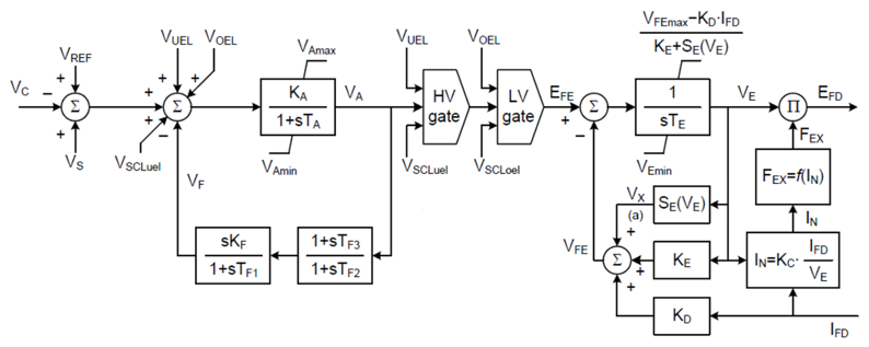
As indicated previously, each of the exciter models have a unique transfer function. The schematic diagram of each is given below.
For more details, see IEEE Standard 421.5-2016.
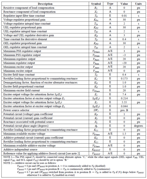
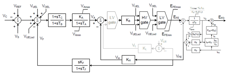
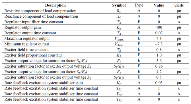
AC1C is an extended version of AC1A to include appropriate connections for summation point, over- and under-excitation limiters, and exciter’s lower and upper limits (VEmin and VFEmax).
Where,

AC2C is an extended version of AC2A to include appropriate connections for summation point, over- and under-excitation limiters, and exciter’s lower limit (VEmin).
Where,
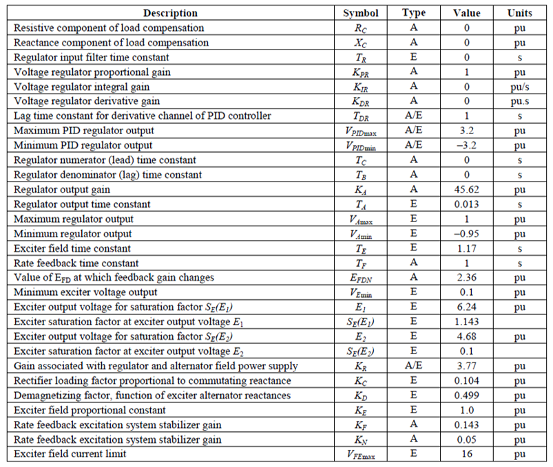
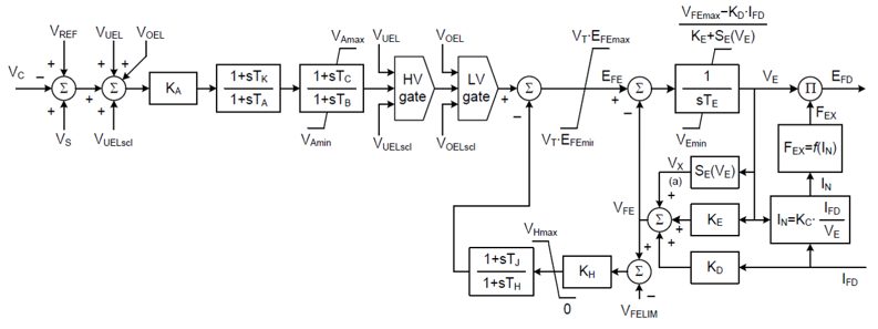
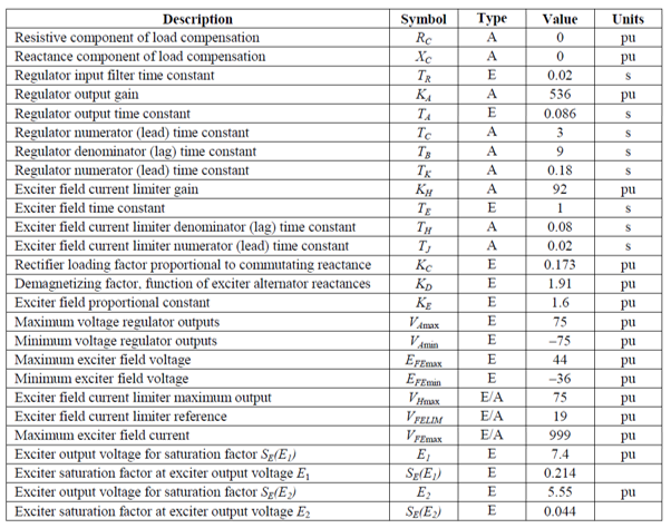
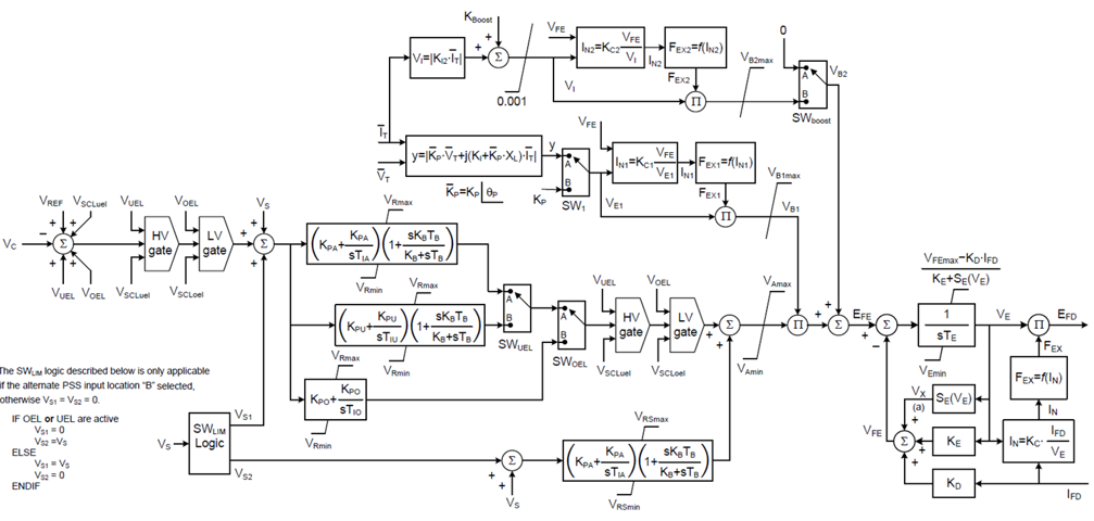
AC3C is an extended version of AC3A to include appropriate connections for summation point, over- and under-excitation limiters, and a PID controller.
Where,
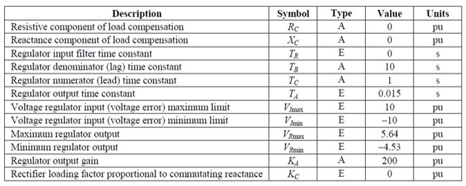
AC4C is an extended version of AC4A to include appropriate connections for summation point, over- and under-excitation limiters.

Where,
AC5C is an extended version of AC5A to include appropriate connections for summation point, over- and under-excitation limiters, and rotating exciter representation.
Where,
AC6C is an extended version of AC6A to include appropriate connections for summation point, over- excitation and under-excitation limiters.
Where,
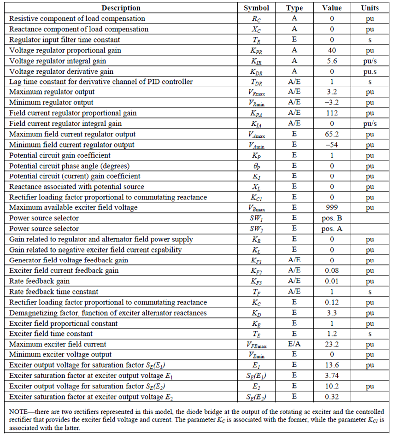
AC7C is an extended version of AC7B to include appropriate connections for summation point, over- and under-excitation limiters, and more flexible representation of the power source for the controlled rectifier connected to the field winding of the rotating exciter.
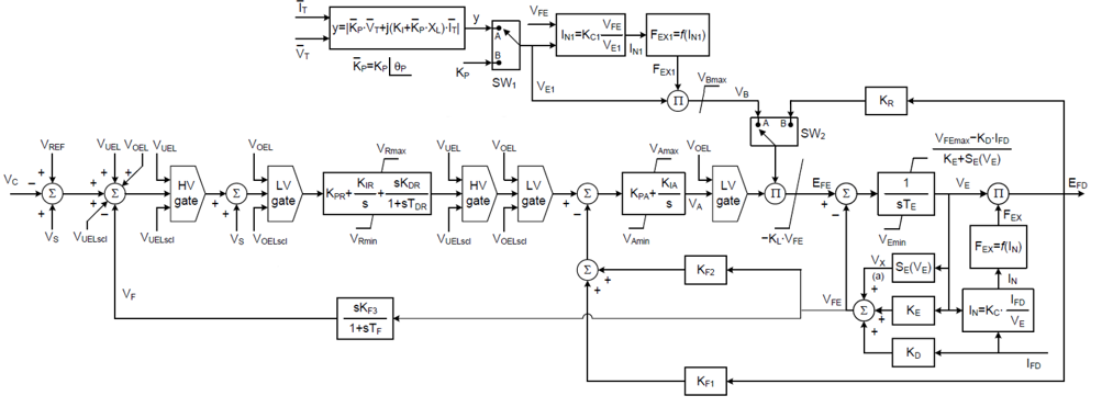
Where,
AC8C is an extended version of AC8B to include appropriate connections for summation point, over- and under-excitation limiters, and more flexible representation of the power source for the controlled rectifier connected to the field winding of the rotating exciter.
Where,
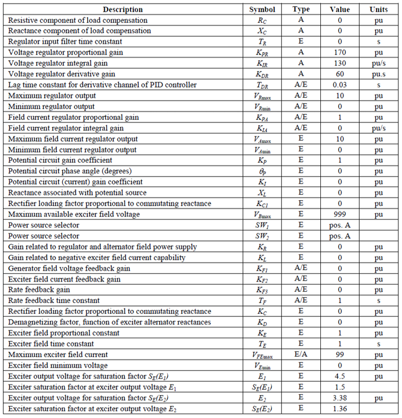
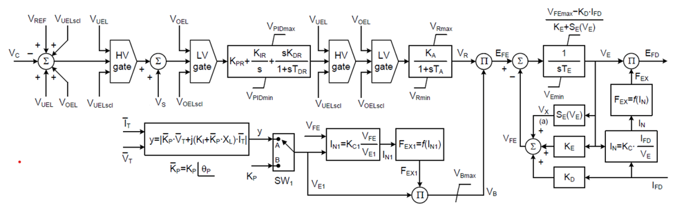
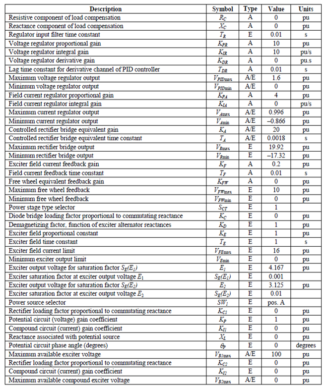
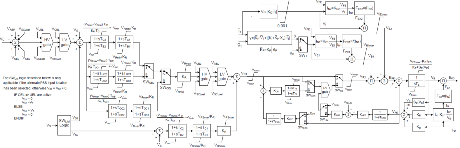
AC9C is a new model introduced to the exciter family in the IEEE Standard 421.5-2016 that consists of a PID voltage regulator followed by a PI current regulator in cascade. It also includes appropriate connections for summation point, over-excitation and under-excitation limiters.
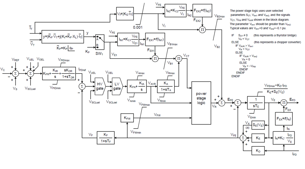
Where,
Sample data for AC9C Thyristor converter excitation system is shown below:
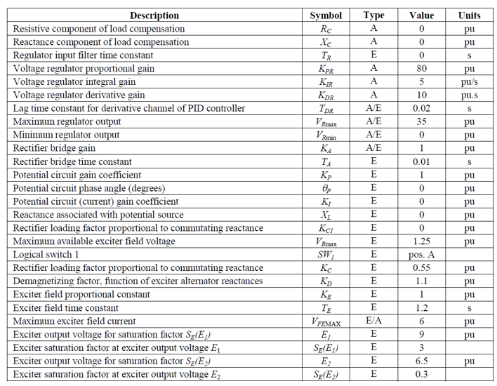
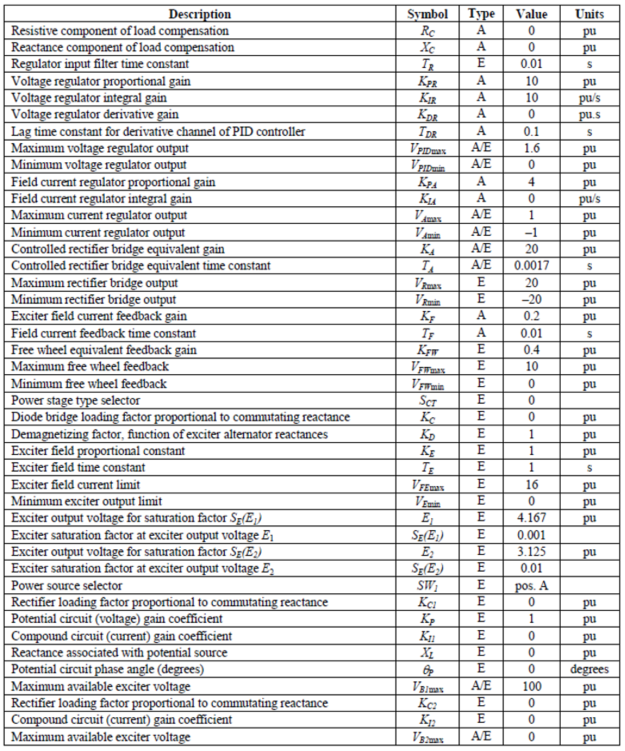
Sample data for AC9C Chopper converter excitation system is shown below:
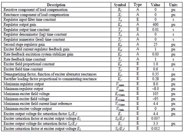
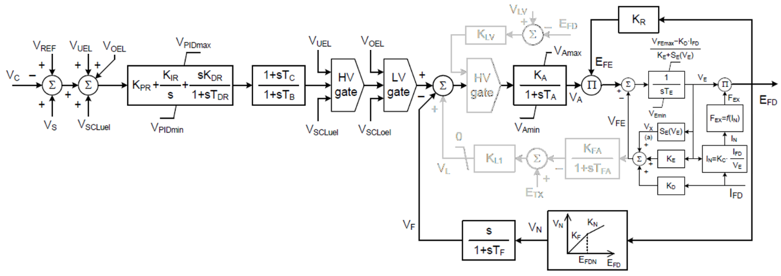
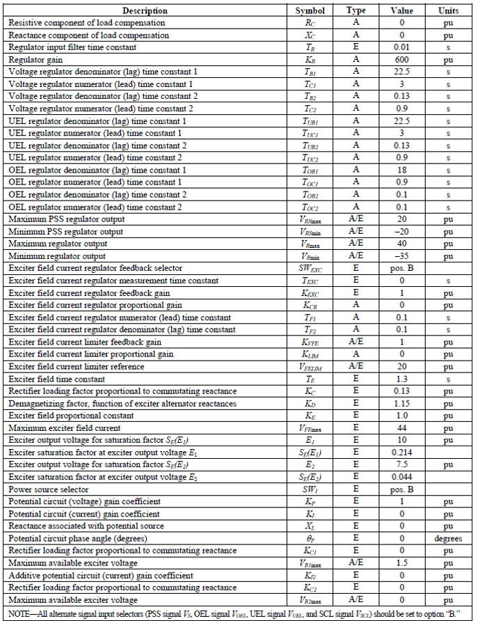
AC10C is a new model introduced to the exciter family in the IEEE Standard 421.5-2016 that consists of two lead-lag elements for the AVR. It also includes appropriate connections for summation point, over-excitation and under-excitation limiters.
Where,
Sample data for AC10C excitation system is shown below:
AC11C is a new model introduced to the exciter family in the IEEE Standard 421.5-2016 that consists of compound circuits for a fast fault recovery. It also includes appropriate connections for summation point, over-excitation and under-excitation limiters.
Where,
Sample data for AC11C excitation system is shown below: