Single Input Power System Stabilizer (PSS1A)
IEEE Power System Stabilizer Type PSS2C
IEEE Power System Stabilizer Type PSS3C
IEEE Power System Stabilizer Type PSS4C
IEEE Power System Stabilizer Type PSS5C
IEEE Power System Stabilizer Type PSS6C
IEEE Power System Stabilizer Type PSS7C
IEEE Discontinuous Excitation Control Type DEC1A
IEEE Discontinuous Excitation Control Type DEC2A
IEEE Discontinuous Excitation Control Type DEC3A
As indicated, each of the power system stabilizer models and discontinuous excitation control models have a unique transfer function. The schematic diagram of each is given below.
For more details, see IEEE Standard 421.5-2016.
Where,
|
A1, A2 = |
Filter constants |
|
KS = |
PSS gain [pu] |
|
T1 = |
First Lead time constant [s] |
|
T2 = |
First Lag time constant [s] |
|
T4 = |
Second Lag time constant [s] |
|
T3 = |
Second Lead time constant [s] |
|
T5 = |
Washout time constant [s] |
|
T6 = |
Transducer time constant [s] |
|
VRMAX, VRMIN = |
Maximum and minimum regulator outputs [pu] |
|
VS1 = |
Input |
|
VST = |
Output [pu] |
|
VSTMAX, VSTMIN = |
PSS output maximum and minimum limits [pu] |
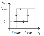
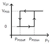
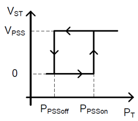
PSS2C is an extended version of PSS2A from IEEE Standard 421.5-1992 and PSS2B from the IEEE Standard 421.5-2005. The PSS2C model shown in the figure below can be used to represent a variety of dual-input stabilizers, which normally use combinations of power and speed (or frequency or compensated frequency) to derive the stabilizing signal. Unlike PSS2B, it allows the representation of the PSS output logic associated with the generator active power output PT, i.e., the PSS output depends on the generator active power output as compared to the thresholds PPSSon and PPSSoff. These threshold values are used to define a hysteresis.
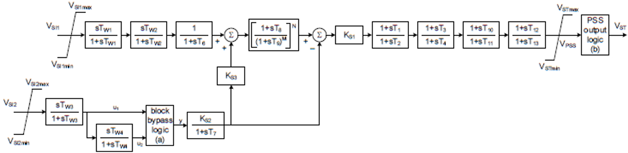
The washout block should be bypassed if the associated time constant is set to zero:
IF TW4=0 THEN
y=u1
ELSE
y=u2
ENDIF
The PSS output logic uses user-selected parameters PPSSon and PPSSoff. It also uses signal VPSS, shown in the block diagram, and the generator electrical power output PT. The output logic implements the following hysteresis to define the output signal VST:
As PSS2C is an extended version of PSS2A as well as PSS2B:
The tables below give the sample data for PSS2C for some specific excitation system models:
For the AC6C & ST1C model:
| Description | Symbol | Type | Value | Units |
|
PSS Gain |
KS1 | A | 20 | pu |
|
PSS Gain |
KS2 | E/A | a | pu |
|
PSS Gain |
KS3 | E | 1 | pu |
|
PSS Transducer Time Constant |
T6 | E | 0.0 | s |
|
PSS Transducer Time Constantb |
T7 | A | 10 | s |
|
PSS Washout Time Constant |
Tw1 | A | 10 | s |
|
PSS Washout Time Constant |
Tw2 | A | 10 | s |
|
PSS Washout Time Constant |
Tw3 | A | 10 | s |
|
PSS Washout Time Constant |
Tw4 | A | c | s |
|
PSS Transducer Time Constant |
T8 | A | 0.3 | s |
|
PSS Washout Time Constant |
T9 | A | 0.15 | s |
|
PSS Transducer Time Constant Exponent |
M | A | 2 | |
|
PSS Transducer Time Constant Exponent |
N | A | 4 | |
|
PSS Numerator (lead) Compensating Time Constant (first block) |
T1 | A | 0.16 | s |
|
PSS Denominator (lag) Compensating Time Constant (first block) |
T2 | A | 0.02 | s |
|
PSS Numerator (lead) Compensating Time Constant (second block) |
T3 | A | 0.16 | s |
|
PSS Denominator (lag) Compensating Time Constant (second block) |
T4 | A | 0.02 | s |
|
PSS Numerator (lead) Compensating Time Constant (third block) |
T10 | A | d | s |
|
PSS Denominator (lag) Compensating Time Constant (third block) |
T11 | A | d | s |
|
PSS Numerator (lead) Compensating Time Constant (fourth block) |
T12 | A | e | s |
|
PSS Denominator (lag) Compensating Time Constant (fourth block) |
T13 | A | e | s |
|
Maximum PSS Output |
VSTmax | A | 0.20 | pu |
|
Minimum PSS Output |
VSTmin | A | -0.066 | pu |
|
Input Signal # 1 Maximum Limit |
VSI1max | A | 2 | pu |
|
Input Signal # 1 Minimum Limit |
VSI1min | A | -2 | pu |
|
Input Signal # 2 Maximum Limit |
VSI2max | A | 2 | pu |
|
Input Signal # 2 Minimum Limit |
VSI2min | A | -2 | pu |
|
Generator MW Threshold for PSS Activation |
PPSSon | A | 0 | pu |
|
Generator MW Threshold for PSS De-activation |
PPSSoff | A | 0 | pu |
Notes:
PSS settings depend not only on the excitation system model and parameters, but also on the generator model. These PSS parameters might not work properly for different generator models, even if the excitation system model remains the same.
For the AC7C model:
| Description | Symbol | Type | Value | Units |
|
PSS Gain |
KS1 | A | 5 | pu |
|
PSS Gain |
KS2 | E/A | a | pu |
|
PSS Gain |
KS3 | E | 1 | pu |
|
PSS Transducer Time Constant |
T6 | E | 0.0 | s |
|
PSS Transducer Time Constantb |
T7 | A | 10 | s |
|
PSS Washout Time Constant |
Tw1 | A | 10 | s |
|
PSS Washout Time Constant |
Tw2 | A | 10 | s |
|
PSS Washout Time Constant |
Tw3 | A | 10 | s |
|
PSS Washout Time Constant |
Tw4 | A | c | s |
|
PSS Transducer Time Constant |
T8 | A | 0.5 | s |
|
PSS Washout Time Constant |
T9 | A | 0.1 | s |
|
PSS Transducer Time Constant Exponent |
M | A | 5 | |
|
PSS Transducer Time Constant Exponent |
N | A | 1 | |
|
PSS Numerator (lead) Compensating Time Constant (first block) |
T1 | A | 0.16 | s |
|
PSS Denominator (lag) Compensating Time Constant (first block) |
T2 | A | 0.04 | s |
|
PSS Numerator (lead) Compensating Time Constant (second block) |
T3 | A | 0.16 | s |
|
PSS Denominator (lag) Compensating Time Constant (second block) |
T4 | A | 0.04 | s |
|
PSS Numerator (lead) Compensating Time Constant (third block) |
T10 | A | 0.18 | s |
|
PSS Denominator (lag) Compensating Time Constant (third block) |
T11 | A | 0.03 | s |
|
PSS Numerator (lead) Compensating Time Constant (fourth block) |
T12 | A | d | s |
|
PSS Denominator (lag) Compensating Time Constant (fourth block) |
T13 | A | d | s |
|
Maximum PSS Output |
VSTmax | A | 0.10 | pu |
|
Minimum PSS Output |
VSTmin | A | -0.10 | pu |
|
Input Signal # 1 Maximum Limit |
VSI1max | A | 2 | pu |
|
Input Signal # 1 Minimum Limit |
VSI1min | A | -2 | pu |
|
Input Signal # 2 Maximum Limit |
VSI2max | A | 2 | pu |
|
Input Signal # 2 Minimum Limit |
VSI2min | A | -2 | pu |
|
Generator MW Threshold for PSS Activation |
PPSSon | A | 0 | pu |
|
Generator MW Threshold for PSS De-activation |
PPSSoff | A | 0 | pu |
Notes:
PSS settings depend not only on the excitation system model and parameters, but also on the generator model. These PSS parameters might not work properly for different generator models, even if the excitation system model remains the same.
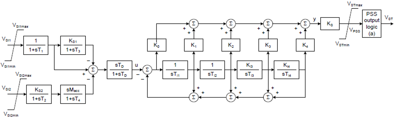
PSS3C is an extended version of PSS3B from the IEEE Standard 421.5-2005. The PSS3C model shown in the figure below has dual inputs, usually generator electrical power output (VSI1 = PT) and rotor angular speed deviation (VSI2 = Δω). The signals are used to derive an equivalent mechanical power signal. By properly combining this signal with electrical power a signal proportional to accelerating power is produced.
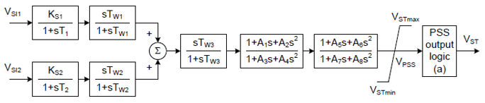
The PSS output logic uses user-selected parameters PPSSon and PPSSoff. It also uses signal VPSS, shown in the block diagram, and the generator electrical power output PT. The output logic implements the following hysteresis to define the output signal VST:
As PSS3C is an extended version of PSS3B, any PSS represented by the PSS3B model could also be represented by the PSS3C model, by setting the PSS3C parameters associated with the PSS output logic (PPSSon and PPSSoff) to zero.
The table below gives the sample data for PSS3C:
| Description | Symbol | Type | Value | Units |
|
PSS Gain (input channel 1) |
KS1 | A | 1 | pu |
|
PSS Gain (input channel 2) |
KS2 | A | 0 | pu |
|
PSS Transducer Time Constant (input channel 1) |
T1 | E/A | 0.02 | s |
|
PSS Transducer Time Constant (input channel 2) |
T2 | E/A | 1.5 | s |
|
PSS Washout Time Constant (input channel 1) |
Tw1 | A | 1.5 | s |
|
PSS Washout Time Constant (input channel 2) |
Tw2 | A | 1.5 | s |
|
PSS Washout Time Constant (combined channels) |
Tw3 | A | 0 | s |
|
PSS Numerator Coefficient (first block) |
A1 | A | 0 | |
|
PSS Numerator Coefficient (first block) |
A2 | A | 0 | |
|
PSS Denominator Coefficient (first block) |
A3 | A | 0 | |
|
PSS Denominator Coefficient (first block) |
A4 | A | 0 | |
|
PSS Numerator Coefficient (second block) |
A5 | A | 0 | |
|
PSS Numerator Coefficient (second block) |
A6 | A | 0 | |
|
PSS Denominator Coefficient (second block) |
A7 | A | 0 | |
|
PSS Denominator Coefficient (second block) |
A8 | A | 0 | |
|
PSS Numerator (lead) Compensating Time Constant (fourth block) |
T12 | A | d | s |
|
PSS Denominator (lag) Compensating Time Constant (fourth block) |
T13 | A | d | s |
|
Maximum PSS Output |
VSTmax | A | 0.10 | pu |
|
Minimum PSS Output |
VSTmin | A | -0.10 | pu |
|
Generator MW Threshold for PSS Activation |
PPSSon | A | 0 | pu |
|
Generator MW Threshold for PSS De-activation |
PPSSoff | A | 0 | pu |
PSS4C is an extended version of PSS4B from the IEEE Standard 421.5-2005. The PSS4C model’s structure is based on multiple working frequency bands as shown in the figure below. Four separate bands respectively dedicated to the very low, low, intermediate, and high-frequency modes of oscillations are used in this delta-omega (speed input) PSS.
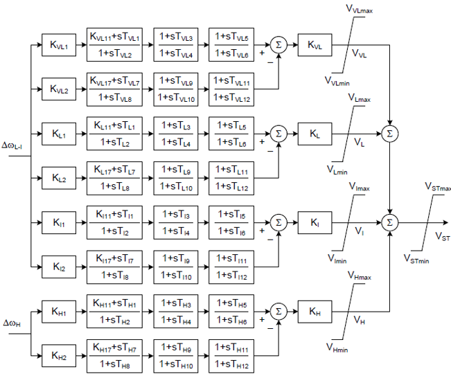
The PSS4C measures the rotor speed deviation in two different ways. The input signal Δω(L-I) feeds the very low, low, and intermediate bands while the input signal ΔωH is dedicated to the high-frequency band. The equivalent model of these two-speed transducers is shown in the figure below. Tuneable notch filters Ni(s), can be used for turbo-generators with well-tuned notch filters attenuating PSS gain at torsional mode frequencies, generally above 10 Hz, as shown below:
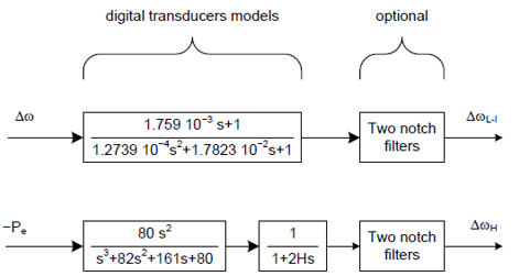

Where,
ωni is the filter frequency
Bωi is the filter 3 dB bandwidth
As PSS4C is an extended version of PSS4B, any PSS represented by the PSS4B model could also be represented by the PSS4C model, by setting the PSS4C parameters in order to ignore the very low-frequency band. This is easily done by setting the gain KVL equal to zero.
The table below gives the sample data for PSS4C:
| Description | Symbol | Type | Value | Units |
|
Very Low Band Gain |
KVL | A | 0.5 | pu |
|
Very Low Band Differential Filter Gain |
KVL1 | A | 66 | pu |
|
Very Low Band First Lead-lag Block Coefficient |
KVL11 | A | 1 | pu |
|
Very Low Band Numerator Time Constant (first lead-lag block) |
TVL1 | A | 12.1 | s |
|
Very Low Band Denominator Time Constant (first lead-lag block) |
TVL2 | A | 14.5 | s |
|
Very Low Band Numerator Time Constant (second lead-lag block) |
TVL3 | A | 0 | s |
|
Very Low Band Denominator Time Constant (second lead-lag block) |
TVL4 | A | 0 | s |
|
Very Low Band Numerator Time Constant (third lead-lag block) |
TVL5 | A | 0 | s |
|
Very Low Band Denominator Time Constant (third lead-lag block) |
TVL6 | A | 0 | s |
|
Very Low Band Differential Filter Gain |
KVL2 | A | 66 | pu |
|
Very Low Band First Lead-lag Block Coefficient |
KVL17 | A | 1 | pu |
|
Very Low Band Numerator Time Constant (first lead-lag block) |
TVL7 | A | 14.5 | s |
|
Very Low Band Denominator Time Constant (first lead-lag block) |
TVL8 | A | 17.4 | s |
|
Very Low Band Numerator Time Constant (second lead-lag block) |
TVL9 | A | 0 | s |
|
Very Low Band Denominator Time Constant (second lead-lag block) |
TVL10 | A | 0 | s |
|
Very Low Band Numerator Time Constant (third lead-lag block) |
TVL11 | A | 0 | s |
|
Very Low Band Denominator Time Constant (third lead-lag block) |
TVL12 | A | 0 | s |
|
Very Low Band Upper Limit |
VVLmax | A | 0.01 | pu |
|
Very Low Band Lower Limit |
VVLmin | A | -0.01 | pu |
|
Low Band Gain |
KL | A | 3 | pu |
|
Low Band Differential Filter Gain |
KL1 | A | 66 | pu |
|
Low Band First Lead-lag Block Coefficient |
KL11 | A | 1 | pu |
|
Low Band Numerator Time Constant (first lead-lag block) |
TL1 | A | 1.73 | s |
|
Low Band Denominator Time Constant (first lead-lag block) |
TL2 | A | 2.075 | s |
|
Low Band Numerator Time Constant (second lead-lag block) |
TL3 | A | 0 | s |
|
Low Band Denominator Time Constant (second lead-lag block) |
TL4 | A | 0 | s |
|
Low Band Numerator Time Constant (third lead-lag block) |
TL5 | A | 0 | s |
|
Low Band Denominator Time Constant (third lead-lag block) |
TL6 | A | 0 | s |
|
Low Band Differential Filter Gain |
KL2 | A | 66 | pu |
|
Low Band First Lead-lag Block Coefficient |
KL17 | A | 1 | pu |
|
Low Band Numerator Time Constant (first lead-lag block) |
TL7 | A | 2.075 | s |
|
Low Band Denominator Time Constant (first lead-lag block) |
TL8 | A | 2.491 | s |
|
Low Band Numerator Time Constant (second lead-lag block) |
TL9 | A | 0 | s |
|
Low Band Denominator Time Constant (second lead-lag block) |
TL10 | A | 0 | s |
|
Low Band Numerator Time Constant (third lead-lag block) |
TL11 | A | 0 | s |
|
Low Band Denominator Time Constant (third lead-lag block) |
TL12 | A | 0 | s |
|
Low Band Upper Limit |
VLmax | A | 0.075 | pu |
|
Low Band Lower Limit |
VLmin | A | -0.075 | pu |
|
Intermediate Band Gain |
KI | A | 20 | pu |
|
Intermediate Band Differential Filter Gain |
KI1 | A | 66 | pu |
|
Intermediate Band First Lead-lag Block Coefficient |
KI11 | A | 1 | pu |
|
Intermediate Band Numerator Time Constant (first lead-lag block) |
TI1 | A | 0.2018 | s |
|
Intermediate Band Denominator Time Constant (first lead-lag block) |
TI2 | A | 0.2421 | s |
|
Intermediate Band Numerator Time Constant (second lead-lag block) |
TI3 | A | 0 | s |
|
Intermediate Band Denominator Time Constant (second lead-lag block) |
TI4 | A | 0 | s |
|
Intermediate Band Numerator Time Constant (third lead-lag block) |
TI5 | A | 0 | s |
|
Intermediate Band Denominator Time Constant (third lead-lag block) |
TI6 | A | 0 | s |
|
Intermediate Band Differential Filter Gain |
KI2 | A | 66 | pu |
|
Intermediate Band First Lead-lag Block Coefficient |
KI17 | A | 1 | pu |
|
Intermediate Band Numerator Time Constant (first lead-lag block) |
TI7 | A | 0.2421 | s |
|
Intermediate Band Denominator Time Constant (first lead-lag block) |
TI8 | A | 0.2906 | s |
|
Intermediate Band Numerator Time Constant (second lead-lag block) |
TI9 | A | 0 | s |
|
Intermediate Band Denominator Time Constant (second lead-lag block) |
TI10 | A | 0 | s |
|
Intermediate Band Numerator Time Constant (third lead-lag block) |
TI11 | A | 0 | s |
|
Intermediate Band Denominator Time Constant (third lead-lag block) |
TI12 | A | 0 | s |
|
Intermediate Band Upper Limit |
VImax | A | 0.6 | pu |
|
Intermediate Band Lower Limit |
VImin | A | -0.6 | pu |
|
High Band Gain |
KH | A | 80 | pu |
|
High Band Differential Filter Gain |
KH1 | A | 66 | pu |
|
High Band First Lead-lag Block Coefficient |
KH11 | A | 1 | pu |
|
High Band Numerator Time Constant (first lead-lag block) |
TH1 | A | 0.01345 | s |
|
High Band Denominator Time Constant (first lead-lag block) |
TH2 | A | 0.01614 | s |
|
High Band Numerator Time Constant (second lead-lag block) |
TH3 | A | 0 | s |
|
High Band Denominator Time Constant (second lead-lag block) |
TH4 | A | 0 | s |
|
High Band Numerator Time Constant (third lead-lag block) |
TH5 | A | 0 | s |
|
High Band Denominator Time Constant (third lead-lag block) |
TH6 | A | 0 | s |
|
High Band Differential Filter Gain |
KH2 | A | 66 | pu |
|
High Band First Lead-lag Block Coefficient |
KH17 | A | 1 | pu |
|
High Band Numerator Time Constant (first lead-lag block) |
TH7 | A | 0.01614 | s |
|
High Band Denominator Time Constant (first lead-lag block) |
TH8 | A | 0.01937 | s |
|
High Band Numerator Time Constant (second lead-lag block) |
TH9 | A | 0 | s |
|
High Band Denominator Time Constant (second lead-lag block) |
TH10 | A | 0 | s |
|
High Band Numerator Time Constant (third lead-lag block) |
TH11 | A | 0 | s |
|
High Band Denominator Time Constant (third lead-lag block) |
TH12 | A | 0 | s |
|
High Band Upper Limit |
VHmax | A | 0.60 | pu |
|
High Band Lower Limit |
VHmin | A | -0.60 | pu |
|
Maximum PSS Output |
VSTmax | A | 0.15 | pu |
|
Minimum PSS Output |
VSTmin | A | -0.15 | pu |
NOTE 1: PSS settings depend not only on the excitation system model and parameters, but also on the generator model. These PSS parameters might not work properly for different generator models, even if the excitation system model remains the same.
NOTE 2: Refer to the figure above regarding the input signals for the PSS4C model. This is a dual-input model using rotor speed and generator electrical power output as inputs.
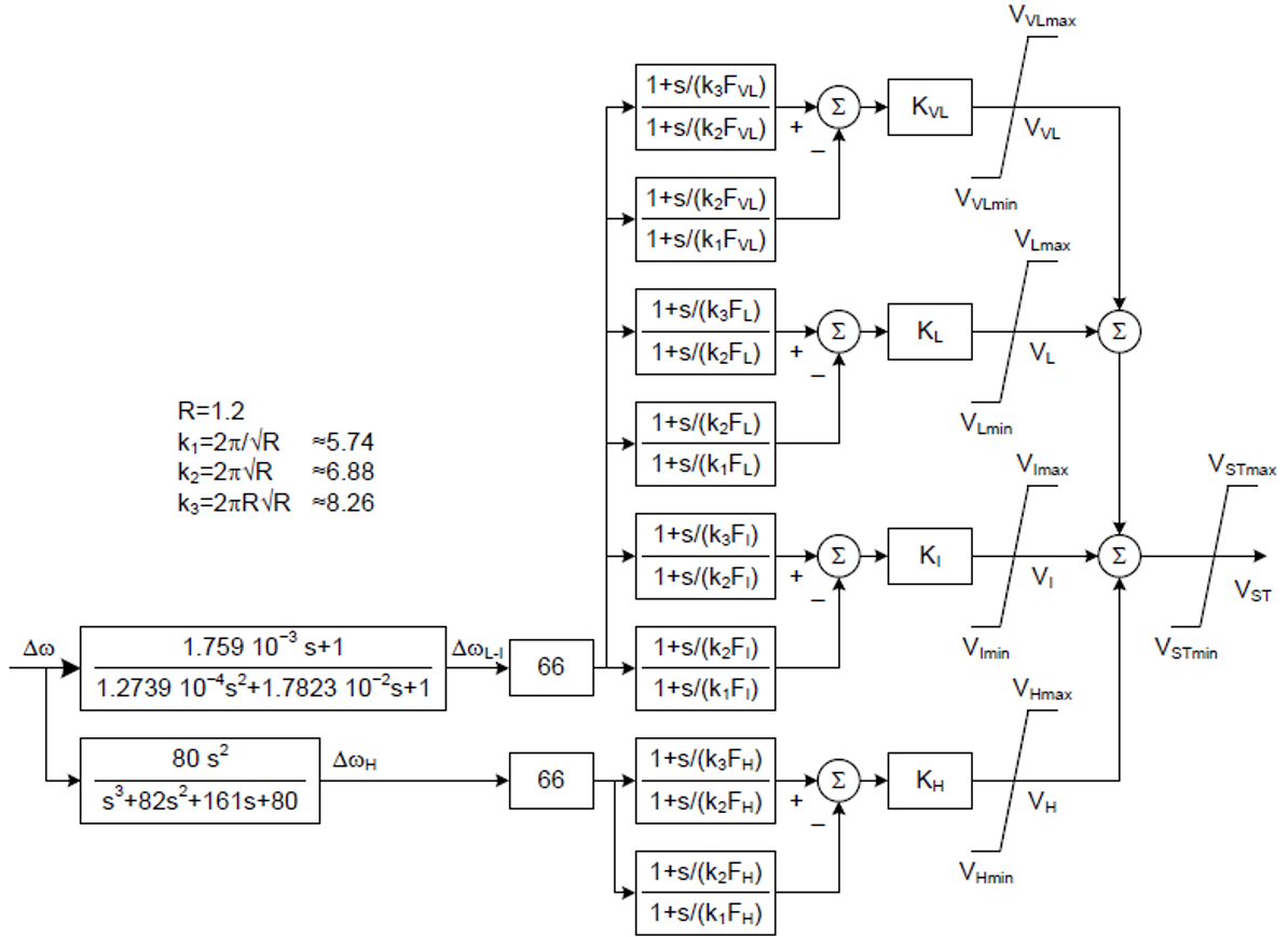
PSS5C represents a simplifying model of the PSS4C. Like the PSS4C, the PSS5C model represents a structure based on multiple working frequency bands as shown in the figure below, but this model uses only four gains and four central frequencies, and the ten limits associated for a total of eighteen parameters. The principal difference is the transducer for which only one input is used as shown in the figure below. Compared with the PSS4C model, this model is easier for tuning studies, but it has a limitation as it cannot represent the rate of change of electrical power (MW/minute) which affects the output of the on-site stabilizer. For studying and stability software where f ≤ 3 Hz, the notch filters could be omitted.
The table below gives the sample data for PSS5C:
| Description | Symbol | Type | Value | Units |
|
Very Low Band Gain |
KVL | A | 0.5 | pu |
|
Very Low Band Central Frequency |
KVL1 | A | 0.01 | Hz |
|
Very Low Band Upper Limit |
VVLmax | A | 0.01 | pu |
|
Very Low Band Lower Limit |
VVLmin | A | -0.01 | pu |
|
Low Band Gain |
KL | A | 3 | pu |
|
Low Band Central Frequency |
KL1 | A | 0.07 | Hz |
|
Low Band Upper Limit |
VLmax | A | 0.075 | pu |
|
Low Band Lower Limit |
VLmin | A | -0.075 | pu |
|
Intermediate Band Gain |
KI | A | 20 | pu |
|
Intermediate Band Central Frequency |
KI1 | A | 0.6 | Hz |
|
Intermediate Band Upper Limit |
VImax | A | 0.60 | pu |
|
Intermediate Band Lower Limit |
VImin | A | -0.60 | pu |
|
High Band Gain |
KH | A | 80 | pu |
|
High Band Central Frequency |
KH1 | A | 9 | Hz |
|
High Band Upper Limit |
VHmax | A | 0.60 | pu |
|
High Band Lower Limit |
VHmin | A | -0.60 | pu |
| k1 | A | 5.736 | ||
| k2 | A | 6.883 | ||
| k3 | A | 8.259 | ||
|
Maximum PSS Output |
VSTmax | A | 0.15 | pu |
|
Minimum PSS Output |
VSTmin | A | -0.15 | pu |
NOTE 1: PSS settings depend not only on the excitation system model and parameters, but also on the generator model. These PSS parameters might not work properly for different generator models, even if the excitation system model remains the same.
NOTE 2: Refer to the figure above regarding the input signals for the PSS5C model. This is a single-input model using rotor speed as the input signal.
PSS6C shown in the figure below is related to the PSS3C. The PSS6C model also has dual inputs, usually generator electrical power output (VSI1 = PT) and rotor angular speed deviation (VSI2 = Δω). The signals are used to derive an equivalent mechanical power signal. By properly combining this signal with electrical power a signal proportional to accelerating power is produced.
The PSS output logic uses user-selected parameters PPSSon and PPSSoff. It also uses signal VPSS, shown in the block diagram, and the generator electrical power output PT. The output logic implements the following hysteresis to define the output signal VST:
It is possible to convert parameters from a PSS3B model into a PSS6C model and vice-versa, but this is not a trivial task, as it might require solving polynomials equations of up to fourth order. For details, see IEEE Standard 421.5-2016.
The table below gives the sample data for PSS6C:
| Description | Symbol | Type | Value | Units |
|
PSS Gain (input signal 1) |
KS1 | A | 20 | pu |
|
PSS Transducer Time Constant (input signal 1) |
T1 | E/A | 0.01 | s |
|
PSS Time Constant (input signal 1) |
T3 | A | 0.4405 | s |
|
PSS Gain (input signal 2) |
KS2 | E/A | 1 | pu |
|
PSS Washout Time Constant (input signal 2) |
Macc | A | 20.6838 | s |
|
PSS Transducer Time Constant (input signal 2) |
T2 | E/A | 0.01 | s |
|
PSS Time Constant (input signal 2) |
T4 | A | 0.4405 | s |
|
PSS Washout Time Constant |
TD | A | 1.7809 | s |
|
PSS Canonical Gain 0 |
K0 | A | 1.3322 | pu |
|
PSS Canonical Gain 1 |
K1 | A | 0.2903 | pu |
|
PSS Canonical Gain 2 |
K2 | A | 0.7371 | pu |
|
PSS Canonical Gain 3 |
K3 | A | 0.0813 | pu |
|
PSS Canonical Gain 4 |
K4 | A | 0 | pu |
|
PSS Third Block Gaina |
Ki3 | A | 1 | pu |
|
PSS Fourth Block Gainb |
Ki4 | A | 0 | pu |
|
PSS Main Block Gain |
K5 | A | 1 | pu |
|
PSS Time Constant (first block) |
T1 | A | 0.16 | s |
|
PSS Time Constant (second block) |
T3 | A | 0.16 | s |
|
PSS Time Constant (third block) |
T10 | A | d | s |
|
PSS Time Constant (fourth block) |
T12 | A | e | s |
|
Maximum PSS Output |
VSTmax | A | 0.05 | pu |
|
Minimum PSS Output |
VSTmin | A | -0.05 | pu |
|
Input Signal # 1 Maximum Limit |
VST1max | A | 2 | pu |
|
Input Signal # 1 Minimum Limit |
VST1min | A | -2 | pu |
|
Input Signal # 2 Maximum Limit |
VST2max | A | 2 | pu |
|
Input Signal # 2 Minimum Limit |
VST2min | A | -2 | pu |
|
Generator MW Threshold for PSS Activation |
PPSSon | A | 0.21 | pu |
|
Generator MW Threshold for PSS De-activation |
PPSSoff | A | 0.19 | pu |
Notes:
PSS settings depend not only on the excitation system model and parameters, but also on the generator model. These PSS parameters might not work properly for different generator models, even if the excitation system model remains the same.
The PSS7C model shown in the figure below is a hybrid of the PSS2C and the PSS6C. The PSS7C model has exactly the same structure of the PSS2C from the dual inputs up to the main PSS gain KS1. The phase compensation, however, is provided by a canonical state equation, similar to what is applied in the PSS6C.
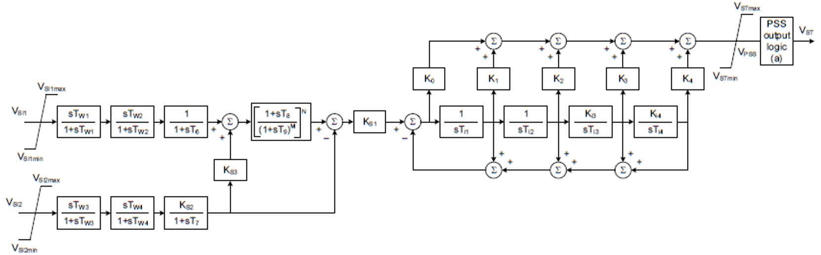
The PSS output logic uses user-selected parameters PPSSon and PPSSoff. It also uses signal VPSS, shown in the block diagram, and the generator electrical power output PT. The output logic implements the following hysteresis to define the output signal VST:
It is possible to convert the parameters of a PSS2C into the canonical form of the PSS7C. On the other hand, it might not be possible to convert the parameters from the PSS7C back to a PSS2C, as the canonical form might result in complex poles or zeros that cannot be represented by the lead-lag blocks in the PSS2C. For details, see IEEE Standard 421.5-2016.
The table below gives the sample data for PSS7C:
| Description | Symbol | Type | Value | Units |
|
PSS Main Gain |
KS1 | A | 50 | pu |
|
PSS Gaina |
KS2 | E/A | 0.7052 | pu |
|
PSS Gain |
KS3 | E | 1 | pu |
|
PSS Transducer Time Constant |
T6 | E | 0 | s |
|
PSS Transducer Time Constantb |
T7 | A | 10 | s |
|
PSS Washout Time Constant |
Tw1 | A | 10 | s |
|
PSS Washout Time Constant |
Tw2 | A | 10 | s |
|
PSS Washout Time Constant |
Tw3 | A | 10 | s |
|
PSS Washout Time Constant |
Tw4 | A | c | s |
|
PSS Transducer Time Constant |
T8 | A | 0.5 | s |
|
PSS Washout Time Constant |
T9 | A | 0.1 | s |
|
Denominator Exponent for Ramp-track Filter |
M | A | 5 | |
|
Overall Exponent for Ramp-track Filter |
N | A | 1 | |
|
PSS Canonical Gain 0 |
K0 | A | 0.399 | pu |
|
PSS Canonical Gain 1 |
K1 | A | 1.8462 | pu |
|
PSS Canonical Gain 2 |
K2 | A | 0.4231 | pu |
|
PSS Canonical Gain 3 |
K3 | A | 0.2104 | pu |
|
PSS Canonical Gain 4 |
K4 | A | 0 | pu |
|
PSS Third Block Gaind |
Ki3 | A | 1 | pu |
|
PSS Fourth Block Gaine |
Ki4 | A | 0 | pu |
|
PSS Time Constant (first block) |
Ti1 | A | 0.03 | s |
|
PSS Time Constant (second block) |
Ti2 | A | 0.0293 | s |
|
PSS Time Constant (third block) |
Ti3 | A | 0.2804 | s |
|
PSS Time Constant (fourth block) |
Ti4 | A | 1 | s |
|
Maximum PSS Output |
VSTmax | A | 0.05 | pu |
|
Minimum PSS Output |
VSTmin | A | -0.05 | pu |
|
Input Signal # 1 Maximum Limit |
VSI1max | A | 2 | pu |
|
Input Signal # 1 Minimum Limit |
VSI1min | A | -2 | pu |
|
Input Signal # 2 Maximum Limit |
VSI2max | A | 2 | pu |
|
Input Signal # 2 Minimum Limit |
VSI2min | A | -2 | pu |
|
Generator MW Threshold for PSS Activation |
PPSSon | A | 0.21 | pu |
|
Generator MW Threshold for PSS De-activation |
PPSSoff | A | 0.10 | pu |
Notes:
PSS settings depend not only on the excitation system model and parameters, but also on the generator model. These PSS parameters might not work properly for different generator models, even if the excitation system model remains the same.
DEC1A discontinuous excitation control, shown in the figure below, is used to represent a scheme that boosts generator excitation to a level higher than that demanded by the voltage regulator and stabilizer immediately following a system fault. For details, see IEEE Standard 421.5-2016.

IF VT>VTM THEN
VP=VOmax
ELSEIF VT<VTN THEN
VP=0
ELSE
VP is unchanged (retains previous value)
ENDIF
DEC2A discontinuous excitation control is shown in the figure below. This system provides transient excitation boosting via an open loop control as initiated by a trigger signal generated remotely. For details, see IEEE Standard 421.5-2016.
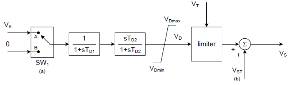
DEC3A discontinuous excitation control is shown in the figure below. In some systems, the PSS output is disconnected from the regulator immediately following a severe fault to prevent the stabilizer from competing with action of voltage regulator during the first swing. This is accomplished in the DEC3A.
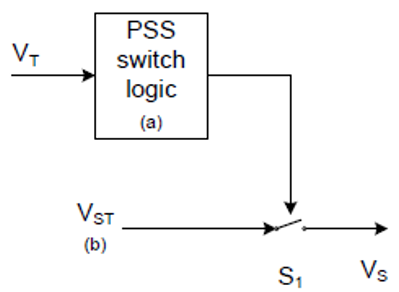
IF VT>VTmin THEN
Open switch S1 and keep it open for the given time TDR
ELSE
Switch S1 is closed, VS=VST
ENDIF