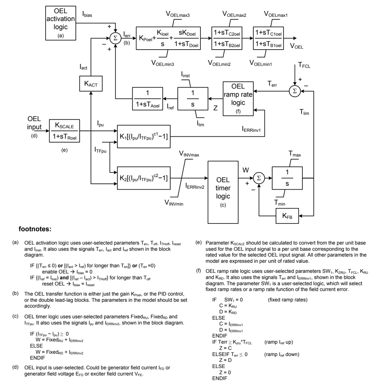
Type OEL3C Summation Point Overexcitation Limiter Model
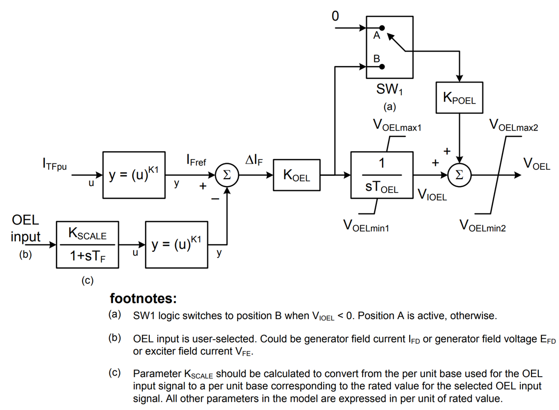
Type OEL4C Summation Point Overexcitation Limiter Model
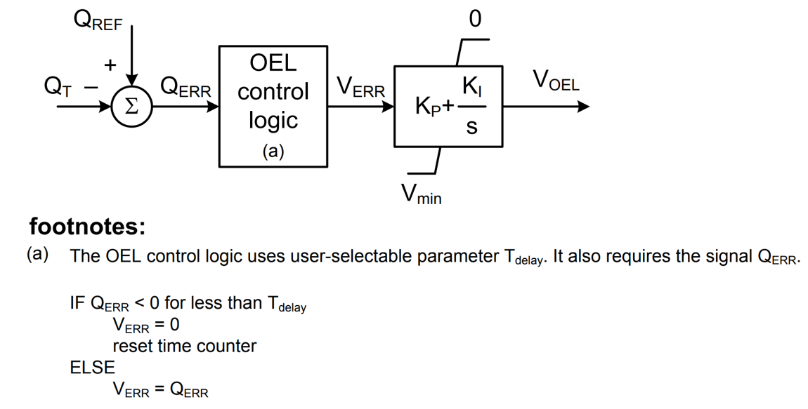
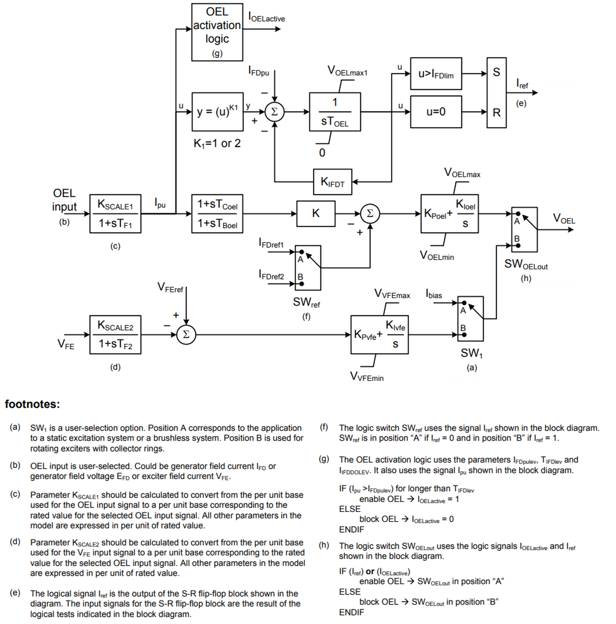
Type OEL5C Takeover Overexcitation Limiter Model
As indicated previously, each of the over excitation limiters have a unique transfer function. The schematic diagram of each is given below.
For further details on background theory for these over excitation limiters, see IEEE Standard 421.5-2016.
Where,
| Description | Symbol | Type | Set 1 | Set 2 | Set 3 | Units |
|
OEL regulator denominator (lag) time constant 1 |
TC1oel | A | 0.1 | 0.2 | 0.1 | s |
|
OEL regulator numerator (lead) time constant 1 |
TB1oel | A | 0.1 | 2 | 0.1 | s |
|
OEL regulator denominator (lag) time constant 2 |
TC2oel | A | 0.1 | 0.1 | 0.1 | s |
|
OEL regulator numerator (lead) time constant 2 |
TB2oel | A | 0.1 | 0.1 | 0.1 | s |
|
OEL PID regulator proportional gain |
KPoel | E | 0.5 | 500 | 0.5 | pu |
|
OEL PID regulator integral gain |
E | E | 0 | 0 | 0 | pu/s |
|
OEL PID regulator differential gain |
KDoel | E | 0 | 0 | 0 | pu |
|
OEL PID regulator differential time constant |
TDoel | E | 0 | 0 | 0 | s |
|
Maximum OEL PID output limit |
VOELmax3 | A/E | 100 | 100 | 100 | pu |
|
Minimum OEL PID output limit |
VOELmin3 | A/E | -100 | -100 | -100 | pu |
|
Maximum OEL lead-lag 1 output limit |
VOELmax2 | A/E | 100 | 100 | 100 | pu |
|
Minimum OEL lead-lag 1 output limit |
VOELmin2 | A/E | -100 | -100 | -100 | pu |
|
Maximum OEL output limit |
VOELmax1 | A/E | 100 | 100 | 100 | pu |
|
Minimum OEL output limit |
VOELmin1 | A/E | -100 | -100 | -100 | pu |
|
OEL reset reference, if OEL is inactivea |
Ireset | A | 0 | 0 | 0 | pu |
|
OEL activation delay timea |
Ten | A | 0.2 | 0.2 | 0.2 | s |
|
OEL reset delay timea |
Toff | A | 0.2 | 0.2 | 0.2 | s |
|
OEL reset threshold valuea |
ITHoff | E | 0.05 | 0.05 | 0.05 | pu |
|
OEL input signal scaling factord |
KSCALE | E | 1 | 1 | 1 | pu |
|
OEL input signal filter time constantd |
TRoel | E | 0.01 | 0.01 | 0.01 | s |
|
OEL actual value scaling factor |
Kact | E | 1 | 1 | 1 | pu |
|
OEL reference for inverse time calculationse |
ITFpu | A/E | 3 | 3 | 3 | pu |
|
OEL instantaneous field current limite |
Iinst | A/E | 6 | 6 | 6 | pu |
|
OEL thermal field current limite |
Ilim | A/E | 3 | 3 | 3 | pu |
|
OEL reference filter time constant |
TAoel | E | 0.04 | 0.04 | 0.04 | s |
|
OEL exponent for calculation of IERRinv1 |
c1 | A/E | 0 | 0 | 0 | |
|
OEL gain for calculation of IERRinv1 |
K1 | A/E | 0 | 0 | 0 | pu/pu |
|
OEL exponent for calculation of IERRinv2b |
c2 | A/E | 2 | 2 | 2 | |
|
OEL gain for calculation of IERRinv2b |
K2 | A/E | 0.0296 | 0.0296 | 0.0296 | pu/pu |
|
OEL maximum inverse time outputb |
VINVmax | A/E | 100 | 100 | 100 | pu |
|
OEL minimum inverse time outputb |
VINVmin | A/E | 0 | 0 | 0 | pu |
|
OEL fixed delay time outputb |
Fixedru | A/E | 0 | 0 | 0 | pu |
|
OEL fixed cooling-down time outputb |
Fixedrd | A/E | -0.001 | -0.001 | -0.001 | pu |
|
OEL timer reference |
TFCL | A | 10 | 1 | 10 | s |
|
OEL timer maximum level |
Tmax | A/E | 6 | 6 | 6 | pu |
|
OEL timer minimum level |
Tmin | A/E | 0 | 0 | 0 | pu |
|
OEL reference feedback gain |
KFB | E | 0 | 0 | 0 | |
|
OEL reference ramp-down ratec |
Krd | E | -1000 | -1000 | -1000 | pu/s |
|
OEL reference ramp-up ratec |
Kru | E | 1000 | 1000 | 1000 | pu/s |
|
OEL thermal reference release thresholdc |
KZRU | E | 0.99 | 0.99 | 0.99 | pu |
|
Rated field currente |
IFDrated | A | 3 | 3 | 3 | pu |
Notes:
Where,
| Description | Symbol | Type | Value | Units |
|
OEL timed field current limiter pick up levela |
ITFpu | A | 3.7 | pu |
|
OEL input signal scaling factora |
KSCALE | A | a | pu |
|
OEL field current measurement time constant |
TF | E/A | 0.02 | s |
|
Exponent for OEL error calculation |
K1 | A | 1 | |
|
OEL gain |
KOEL | A | 1 | pu |
|
OEL integral time constant |
TOEL | A | 24 | s |
|
OEL proportional gain |
KPOEL | A | 1 | pu |
|
OEL integrator maximum output |
VOELmax1 | A | 0.66 | pu |
|
OEL integrator minimum output |
VOELmin1 | A | -1 | pu |
|
OEL maximum output |
VOELmax2 | A | 0 | pu |
|
OEL minimum output |
VOELmin2 | A | -1 | pu |
Notes:
Where,
| Description | Symbol | Type | Value | Units |
|
OEL timed reactive power limiter pick up level |
QREF | A | 0.4 | pu |
|
OEL integral time constant |
Tdelay | A | 20 | s |
|
OEL proportional gain |
KP | A | 1 | pu |
|
OEL integral gain |
KI | A | 1 | pu/s |
|
OEL minimum output |
Vmin | A | -0.2 | pu |
Where,
| Description | Symbol | Type | Set 1 | Set 2 | Set 3 | Units |
|
OEL inverse time integrator pickup level |
IFDpu | A | 1.02 | 1.02 | 1.02 | pu |
|
OEL inverse time limit active level |
IFDlim | A | 6.58 | 6.58 | 6.58 | pu.s |
|
OEL inverse time upper limit |
VOELMAX1 | A | 9.49 | 9.49 | 9.49 | pu.s |
|
OEL inverse time integrator time constant |
TOEL | A | 1 | 1 | 1 | s |
|
OEL inverse time leak gain |
KIFDT | A | 0.0043 | 0.0043 | 0.0043 | pu |
|
OEL lead-lag gain |
K | E | 1 | 1 | 1 | pu |
|
OEL lead time constant |
TCoel | A | 0 | 0.9 | 0 | s |
|
OEL lag time constant |
TBoel | A | 0 | 0.32 | 0 | s |
|
OEL activation logic pickup level |
IFDpulev | A | 1.4 | 1.4 | 1.4 | pu |
|
OEL activation logic timer setpoint |
TIFDlev | A | 1 | 1 | 1 | s |
|
OEL reference 1 |
IFDref1 | A | 1.25 | 1.25 | 1.25 | pu |
|
OEL reference 2 |
IFDref2 | A | 1 | 1 | 1 | pu |
|
OEL proportional gain |
KPoel | A | 0.46 | 2.861 | 1.0753 | pu |
|
OEL integral gain |
KIoel | A | 17.36 | 8.94 | 9.02 | pu/s |
|
OEL PI control upper limit |
VOELmax | A | 1 | 1 | 1 | pu |
|
OEL PI control lower limit |
VOELmin | A | -0.99 | -0.99 | -0.99 | pu |
|
Exciter field current regulator proportional gain |
KPvfe | A | 0 | 1.522 | 0 | pu |
|
Exciter field current regulator integral gain |
KIvfe | A | 0 | 169.1 | 0 | pu/s |
|
Exciter field current regulator upper limit |
VVFEmax | A | 1 | 1 | 1 | pu |
|
Exciter field current regulator lower limit |
VVFEmin | A | -0.999 | -0.999 | -0.999 | pu |
|
Scale factor for OEL input |
KSCALE1 | E | 0.295 | 0.3305 | 0.2296 | |
|
OEL input transducer time constant |
TF1 | A/E | 0 | 0 | 1.22 | s |
|
Scale factor IFEbase/IFErated |
KSCALE2 | E | 0.2317 | 0 | 0 | |
|
Exciter field current transducer time constant |
TF2 | A/E | 0 | 0 | 0 | s |
|
Exciter field current reference setpoint |
VFEref | A | 0 | 2.151 | 0 | pu |
|
OEL reference logic switch |
SW1 | A/E | pos. A | pos. B | pos. A | |
|
OEL reference bias |
Ibias | A/E | 1 | 1 | 2.15 | pu |
|
Exponent for inverse time function |
K1 | A | 1 | 1 | 1 |