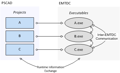
Beginning with PSCAD v4.6, multiple case projects representing multiple parts of a complete electric network, may be run simultaneously as a single simulation. A single electric network may be split so that each electric subsystem is represented by a separate case project, and thereby run using a separate EMTDC process. Each EMTDC process is linked together via an Electric Network Interface (ENI) to form a cohesive simulation that is run from within a single workspace.

Multi-Project Simulation Using the ENI in PSCAD
In terms of runtime information for plotting and online data signal control, PSCAD and EMTDC communicate normally as they would for a single process. There is additional communication between the multiple EMTDC processes in multi-project simulations however. Due to the fact that each EMTDC process is an executable file, each can be launched on its own processor core, enabling parallel simulation of the complete system.
For larger networks containing multiple subsystems, using the ENI can greatly enhance the total simulation speed, especially when the subsystems contain high speed switching devices (i.e. FACTs devices).
The boundaries of electric subsystems in EMTDC are defined via distributed-parameter transmission lines and cables, and so it makes sense that the transmission segments themselves be the linking points in a multi-project simulation. As a very simple example, let us take a slightly modified version of the familiar Cigre Benchmark Model example project. A transmission line has been added to represent the DC interconnection between the two converters (the original was simply an RLC passive network).

Cigre Benchmark Model Example Project with Transmission Line Interconnect
The addition of the transmission line to this system results in a division of the electric network into two, separate subsystems (approximately 25 nodes each). These two sub-networks can be compiled and launched as separate, but dependent processes, due to the natural propagation delay generated by the distributed transmission line. Before this can be accomplished however, the project must be manually split in to two separate project files.
Splitting the project up can be achieved in a number of ways, but the most efficient is to first duplicate the project and then manually modify each one. Doing this for this example results in the following two separate project circuits:
|
|
Rectifier Side Project |
Inverter Side Project |
In order to accommodate this new electric network interface between projects, some changes have been made to the transmission line components. These changes are explained in the following sections.
A few parameters and functionalities exist in both the Overhead Line and Cable configuration, as well as the Overhead Line and Cable interface components in order to accommodate the ENI interface. In the configuration components, two new termination styles have are provided.

Of the four options provided, only Foreign and Alien ends are used when setting up the ENI interface:
Foreign ends: Foreign ends are used to interface between two separate case projects within the same workspace (i.e. instance of PSCAD).
Alien ends: Alien ends are used to interface between two separate case projects within two separate instances of PSCAD.
The interface components contain a few parameters involving the ENI:

These parameters provide information for the Control Signal Carrier function (described below).
Sending/Receiving Signal Dimension: Enter the dimension of both incoming control or outgoing control signal. See Control Signal Carrier for more details.
There is also a parameter provided for using the ENI between separate PSCAD applications:

End Type: This parameter specifies the end type of this side of the transmission line: None, Client or Server. When simulating using two separate PSCAD applications, one instance must act as the server, and the other the client: The case project containing the Overhead Line Configuration component is always designated as the server.
Inevitably when a project is decomposed into separate electrical subsystems, there will be situations where control signals generated in one project are needed in another. The ENI utilizes a concept referred to Control Signal Carrier, which allows control signals to be piped through the transmission line interface, along with the electrical data. Of course, the control signal data arrives at the other end with no time delay.
In the example given above, the Current Order control signal is generated in the inverter case project, and then passed via control signal carrier to the rectifier project.
|
|
|
Project 1 Transmission Line End Exchanging Control Signal Data with Project 2 |
Project 2 Transmission Line End Exchanging Control Signal Data with Project 1 |
Transmission Line Interface Component Parameters |