Description
Input Parameters
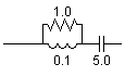
The branch impedance of this filter decreases with increasing frequency. Placing the branch between a line and ground will absorb frequencies above the 'cut-off' frequency. Filter parameters may be entered as R, L & C or Q, f0 & MVAr.
More:
Passive Filter Design
Configuration
Data Entry
Choice
Select RLC Values or MVAR, Fn & Q
Resonant Freq & Q
Q FACTOR (R/w*L)
REAL
Constant
This is the filter quality (a measure of the sharpness of the response)
Base Frequency
Used with Megavars (1-Phase) and Phase Voltage to determine the capacitor value [Hz]
Cut-Off Frequency
The filter cut-off frequency [Hz]
Megavars (1-phase)
Used with Base Frequency and Phase Voltage inputs to determine the appropriate capacitor value [MVAr]
Phase Voltage
Used with Megavars (1-Phase) and Base Frequency inputs to determine the capacitor value [kV RMS]
RLC Values
Resistance
Resistance [W]
Inductance
Inductance [H]
Capacitance
Capacitance [mF]
Internal Output Variables
Name for Filter Current (kA)
Output
Name for the filter current [kA]