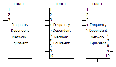
This component creates a multi-port, frequency-dependent network equivalent (FDNE) from given characteristics, such as impedance (Z), admittance (Y) or scattering (S) parameters. This model first approximates the parameters with rational functions, using the Vector Fitting technique. Once the parameters are expressed in rational form (pole/residue) or state-space form, an EMT-type, frequency-dependent network equivalent can be constructed, consisting of admittances and current sources.
In power systems, a Frequency-Dependent Network Equivalent (FDNE) model may typically be used to represent many system types, including wide-band, reduced-order network equivalents, high-frequency power transformers, or short transmission lines; all from frequency sweep measurements/computations. This component can be used to model high-frequency power electronic converters and filters as well.
Input to this component is the frequency-dependent characteristics of the network to be represented by an equivalent, and is provided as a text file. The input data may be given in one of the following formats:
Output from the Interface to Harmonic Impedance Solution (see note below)
Impedance Parameters
Admittance Parameters
Scattering Parameters
Admittance as ABCD Parameters
Scattering as ABCD Parameters
Sequence parameters
NOTE: In the Interface to Harmonic Impedance Solution component, the Impedance Output Type should be set to Phase Impedances.
The component instance number and call number are used to create detailed output files (ex. fdne_<instance number>_<call number>.log) in the project temporary folder. These output files may be useful to diagnose any problems/errors that may occur. The curve-fitting detailed output files are also created for all input methods except, ABCD parameters. The output files fdne_<instance number>_<call number>_Y_MAG.out and fdne_<instance number>_<call number>_Y_ANG.out show the actual/ fitted magnitude and phase data respectively.
The FDNE component can be used to model a portion of a network (i.e. a sub-network) using parameters, such as impedance or admittance (these parameters only represent a passive network). However, the sub-network may consist of active elements, such as voltage sources, etc. The effect of active elements can be modeled by defining power injections at the component terminals. This will give accurate power flow and terminal voltages. When the terminal conditions (voltage, angle, active and reactive power) or current injections are defined, the model automatically calculates the current injections.
More: |
Reference [36] |