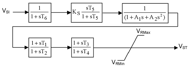
Single Input Power System Stabilizer (PSS1A)
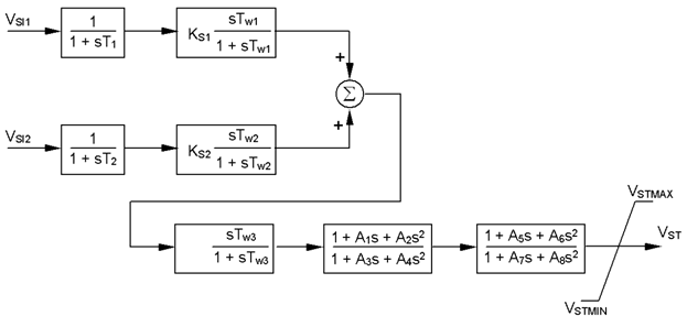
Dual Input Power System Stabilizer (PSS2B)
Dual Input Power System Stabilizer (PSS3B)
Dual Input Power System Stabilizer (PSS4B)
Transient Excitation Booster with Dual Action Terminal Voltage Limiter (DEC1A)
Open Loop Transient Excitation Booster (DEC2A)
Temporary Interrupter of Stabilizing Signal (DEC3A)
As indicated previously, each of these stabilizer models have a unique transfer function. The schematic diagram of each is given below.
Where,
A1, A2 = |
Filter constants |
KS = |
PSS gain [pu] |
T1 = |
First Lead time constant [s] |
T2 = |
First Lag time constant [s] |
T4 = |
Second Lag time constant [s] |
T3 = |
Second Lead time constant [s] |
T5 = |
Washout time constant [s] |
T6 = |
Transducer time constant [s] |
VRMAX, VRMIN = |
Maximum and minimum regulator outputs [pu] |
VS1 = |
Input |
VST = |
Output [pu] |
VSTMAX, VSTMIN = |
PSS output maximum and minimum limits [pu] |

Where,
KS1 = |
PSS gain [pu] |
KS2 = |
Second signal gain [pu] |
KS3 = |
Second signal second gain [pu] |
M, N = |
Integer Filter Constants |
T1 = |
First lead time constant [s] |
T2 = |
First lag time constant [s] |
T3 = |
Second lead time constant [s] |
T4 = |
Second lag time constant [s] |
T5 = |
Third lag time constant [s] |
T6 = |
First signal transducer time constant [s] |
T7 = |
Second signal transducer time constant [s] |
T8 = |
Filter lead time constant [s] |
T9 = |
Filter lag time constant [s] |
T10 = |
Third lead time constant [s] |
T11 = |
PSS lag compensating time constant [s] |
TW1 = |
First signal first washout time [s] |
TW2 = |
First signal second washout time [s] |
TW3 = |
Second signal first washout time [s] |
TW4 = |
Second signal second washout time [s] |
VSI1, VSI2 = |
Inputs [pu] |
VSI1MAX , VSI1MIN = |
First signal maximum and minimum inputs [pu] |
VSI2MAX , VSI2MIN = |
Second signal maximum and minimum inputs [pu] |
VST = |
Output [pu] |
VSTMAX, VSTMIN = |
PSS output Maximum and minimum limits [pu] |
Where,
A1, A2, A3, A4, |
Filter coefficients [s] |
KS1 = |
First input signal gain [pu] |
KS2 = |
Second input signal gain [pu] |
T1 = |
First transducer time constant [s] |
T2 = |
Second transducer time constant [s] |
TW1 = |
First signal washout time constant [s] |
TW2 = |
Second signal washout time constant [s] |
TW3 = |
Washout time constant [s] |
VSI1, VSI2 = |
Inputs [pu] |
|
Output [pu] |
VSTMAX, VSTMIN = |
PSS output maximum and minimum limits [pu] |
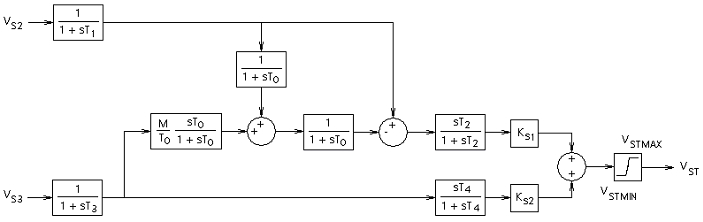
Where,
2H = |
Synchronous machine inertia constant [s] |
KS1 = |
First signal gain [pu] |
KS2 = |
Second signal gain [pu] |
M = |
Synchronous machine inertia constant |
T0 = |
System start-up time constant [s] |
T1 = |
First transducer time constant [s] |
T2 = |
First signal washout time constant [s] |
T3 = |
Second transducer time constant [s] |
T4 = |
Second signal washout time constant [s] |
VS2, VS3 = |
Inputs |
VST = |
Output [pu] |
VSTMAX, VSTMIN = |
PSS output maximum and minimum limits [pu] |
Where,
BWI = |
3dB bandwidth of the notch filter [Hz] |
H = |
Inertia constant [s] |
KH = |
Gain in common branch [pu] |
KH1 = |
Gain in positive branch [pu] |
KH2 = |
Gain in negative branch [pu] |
KH11 = |
Proportional gain in first block [pu] |
KH17 = |
Proportional gain in first block [pu] |
KI = |
Gain in common branch [pu] |
KI1 = |
Gain in positive branch [pu] |
KI2 = |
Gain in negative branch [pu] |
KI11 = |
Proportional gain in first block [pu] |
KI17 = |
Proportional gain in first block [pu] |
KL = |
Gain in common branch [pu] |
KL1 = |
Gain in positive branch [pu] |
KL2 = |
Gain in negative branch [pu] |
KL11 = |
Proportional gain in first block [pu] |
KL17 = |
Proportional gain in first block [pu] |
TH1 = |
Derivative time constant in first block [s] |
TH2 = |
Lag time constant in first block [s] |
TH3 = |
Lead time constant in second block [s] |
TH4 = |
Lag time constant in second block [s] |
TH5 = |
Lead time constant in third block [s] |
TH6 = |
Lag time constant in third block [s] |
TH7 = |
Derivative time constant in first block [s] |
TH8 = |
Lag time constant in first block [s] |
TH9 = |
Lead time constant in second block [s] |
TH10 = |
Lag time constant in second block [s] |
TH11 = |
Lead time constant in third block [s] |
TH12 = |
Lag time constant in third block [s] |
TI1 = |
Derivative time constant in first block [s] |
TI2 = |
Lag time constant in first block [s] |
TI3 = |
Lead time constant in second block [s] |
TI4 = |
Lag time constant in second block [s] |
TI5 = |
Lead time constant in third block [s] |
TI6 = |
Lag time constant in third block [s] |
TI7 = |
Derivative time constant in first block [s] |
TI8 = |
Lag time constant in first block [s] |
TI9 = |
Lead time constant in second block [s] |
TI10 = |
Lag time constant in second block [s] |
TI11 = |
Lead time constant in third block [s] |
TI12 = |
Lag time constant in third block [s] |
TL1 = |
Derivative time constant in first block [s] |
TL2 = |
Lag time constant in first block [s] |
TL3 = |
Lead time constant in second block [s] |
TL4 = |
Lag time constant in second block [s] |
TL5 = |
Lead time constant in third block [s] |
TL6 = |
Lag time constant in third block [s] |
TL7 = |
Derivative time constant in first block [s] |
TL8 = |
Lag time constant in first block [s] |
TL9 = |
Lead time constant in second block [s] |
TL10 = |
Lag time constant in second block [s] |
TL11 = |
Lead time constant in third block [s] |
TL12 = |
Lag time constant in third block [s] |
vHMAX, vHMIN = |
Maximum and minimum limits [pu] |
vIMAX, vIMIN = |
Maximum and minimum limits [pu] |
vLMAX, vLMIN = |
Maximum and minimum limits [pu] |
vST = |
Output [pu] |
vSTMAX, vSTMIN = |
PSS output maximum and minimum limits [pu] |
WNI = |
Tuned frequency of the notch filter [Hz] |

Where,
ESC = |
Speed change reference [pu] |
KAN = |
Integrator gain [pu] |
KETL = |
Terminal voltage limiter gain [pu] |
TAN = |
Integrator time constant [s] |
TD = |
Reset delay time [s] |
TL1 = |
Voltage limiter lead time [s] |
TL2 = |
Voltage limiter lag time [s] |
TW5 = |
DEC washout time constant [s] |
VA = |
Regulator internal voltage [pu] |
VAL = |
Regulator voltage reference [pu] |
VAN = |
Internal signal |
VANMAX = |
Integrator maximum limit [pu] |
VOMAX, VOMIN = |
Terminal voltages maximum and minimum deviation over reference [pu] |
VO, VP = |
Limiter signals [pu] |
VS = |
Output [pu] |
VSMAX, VSMIN = |
PSS plus DEC maximum and minimum limits [pu] |
VST = |
Power system stabilizer output [pu] |
VT = |
Synchronous machine terminal voltage input [pu] |
VTC = |
Terminal voltage level reference [pu] |
vTM, vTN = |
Bang-Bang controller maximum and minimum limits [pu] |
VTLMT = |
Terminal voltage reference [pu] |
W = |
Speed input [pu] |
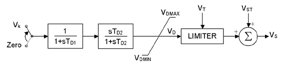
Where,
TD1 = |
Controller time constant [s] |
TD2 = |
DEC washout time constant [s] |
VD = |
Discontinuous controller internal voltage |
VDMAX, VDMIN = |
DEC maximum and minimum limits [pu] |
VK = |
Trigger signal amplitude [pu] |
VS = |
Output [pu] |
VST = |
Power system stabilizer output [pu] |
VT = |
Synchronous machine terminal voltage input [pu] |
VTLIMIT = |
Terminal voltage maximum limit [pu] |
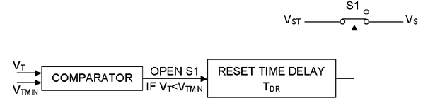
Where,
TDR = |
Reset time delay [s] |
VS = |
Output [pu] |
VST = |
Power system stabilizer output [pu] |
VT = |
Synchronous machine terminal voltage input [pu] |
VTMIN = |
Controller input reference [pu] |
![]()
