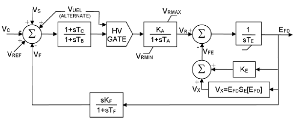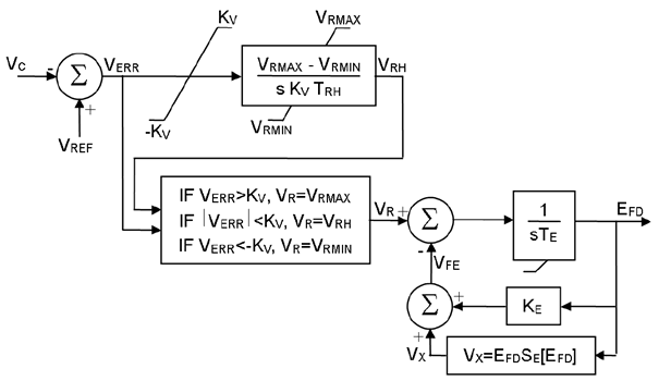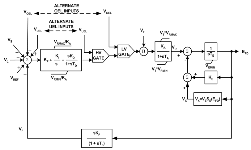
As indicated previously, each of the exciter models have a unique transfer function. The schematic diagram of each is given below.

Where,
|
Exciter voltage for SE1 [pu] |
|
Exciter voltage for SE2 [pu] |
|
Regulator gain [pu] |
|
Exciter constant related to field [pu] |
|
Rate feedback gain [pu] |
|
Exciter saturation function value at the corresponding exciter voltage, EFD [pu] |
|
Saturation at EFD1 [pu] |
|
Saturation at EFD2 [pu] |
|
Regulator time constant [s] |
|
Lag time constant [s] |
|
Lead time constant [s] |
|
Exciter time constant [s] |
|
Rate feedback time constant [s] |
|
Output of terminal voltage transducer and load compensation elements [pu] |
|
Excitation system stabilizer output [pu] |
|
Signal proportional to exciter field current [pu] |
|
Voltage regulator output [pu] |
|
Voltage regulator reference (determined to satisfy initial conditions) [pu] |
|
Maximum and minimum regulator outputs [pu] |
|
Combined power system stabilizer and possibly discontinuous control output after any limits or switching, as summed with terminal voltage and reference signals [pu] |
|
Under-excitation limiter input [pu] |
|
Signal proportional to exciter saturation [pu] |

Where,
|
Exciter voltage for SE1 [pu] |
|
Exciter voltage for SE2 [pu] |
|
Regulator gain [pu] |
|
Exciter constant related to self-excited field [pu] |
|
Rate feedback gain [pu] |
|
Saturation at EFD1 [pu] |
|
Saturation at EFD2 [pu] |
|
Regulator time constant [s] |
|
Lag time constant [s] |
|
Lead time constant [s] |
|
Exciter time constant [s] |
|
Rate feedback time constant [s] |
|
Output of terminal voltage transducer and load compensation elements [pu] |
|
Excitation system stabilizer output [pu] |
|
Signal proportional to exciter field current [pu] |
|
Voltage regulator output [pu] |
|
Voltage regulator reference (determined to satisfy initial conditions) [pu] |
|
Maximum and minimum regulator outputs [pu] |
|
Combined power system stabilizer and possibly discontinuous control output after any limits or switching, as summed with terminal voltage and reference signals [pu] |
|
Synchronous machine terminal voltage [pu] |
|
Under-excitation limiter input [pu] |
|
Signal proportional to exciter saturation [pu] |

Where,
|
Exciter voltage for SE1 [pu] |
|
Exciter voltage for SE2 [pu] |
|
Exciter constant related to self-excited field [pu] |
|
Fast raise/lower setting [pu] |
|
Saturation at EFD1 [pu] |
|
Saturation at EFD2 [pu] |
|
Exciter time constant [s] |
|
Rheostat travel time [s] |
|
Output of terminal voltage transducer and load compensation elements [pu] |
|
Voltage error signal [pu] |
|
Signal proportional to exciter field current [pu] |
|
Voltage regulator output [pu] |
|
Voltage regulator reference (determined to satisfy initial conditions) [pu] |
|
Maximum and minimum regulator outputs [pu] |
|
Signal proportional to exciter saturation [pu] |

Where,
|
Exciter voltage for SE1 [pu] |
|
Exciter voltage for SE2 [pu] |
|
Regulator gain [pu] |
|
Regulator derivative gain [pu] |
|
Exciter constant related to self-excited field [pu] |
|
Rate feedback gain [pu] |
|
Regulator integral gain [pu] |
|
Regulator proportional gain [pu] |
|
Saturation at EFD1 [pu] |
|
Saturation at EFD2 [pu] |
|
Regulator time constant [s] |
|
Regulator derivative time constant [s] |
|
Exciter time constant [s] |
|
Rate feedback time constant [s] |
|
Output of terminal voltage transducer and load compensation elements [pu] |
|
Exciter minimum output voltage [pu] |
|
Exciter voltage back of commutating reactance [pu] |
|
Excitation system stabilizer output [pu] |
|
Voltage regulator output [pu] |
|
Voltage regulator reference (determined to satisfy initial conditions) [pu] |
|
Maximum and minimum regulator outputs [pu] |
|
Combined power system stabilizer and possibly discontinuous control output after any limits or switching, as summed with terminal voltage and reference signals [pu] |
|
Synchronous machine terminal voltage [pu] |
|
Over excitation limiter input [pu] |
|
Under-excitation limiter input [pu] |
|
Signal proportional to exciter saturation [pu] |