Estimation of Armature Reaction Constants
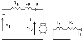
Consider the machine connection shown below:
The terminal voltage, Vt, verses armature current Ia characteristic for this machine, at a constant field current and at a constant speed is shown below:
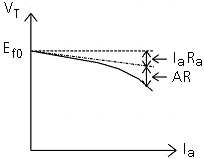
The difference (Ef0 - Vt - RaIa) increases with the armature current Ia. This difference is attributed to the armature reaction (AR). Thus, the effective induced back emf, Ef_e , under this operating condition is:
![]()
The armature reaction is modeled as a drop in the induced armature voltage, due to the demagnetization effects of the field flux caused by the armature current. This drop depends on the speed of the machine, the field current and the armature current. The data specified should correspond to the same speed w1 where the Open Circuit Voltage Characteristics were defined.
The Two Winding DC Machine component models the armature reaction by the following equation:
![]()
Where:
|
|
Field current [pu] |
|
|
Armature current [pu] |
|
|
Constant coefficients |
The coefficients b1 to b9 are estimated through curve fitting techniques. If the data necessary for this computation is not provided by the manufacturer, the following procedure can be used to obtain test data.
Rotate the machine at a constant speed (w1) using a prime mover. Keep the field current (If) constant. Load the machine and measure the terminal voltage, Vt , at different values of armature current, Ia. Calculate the armature reaction, AR, at different Ia values. Ia should range from 0 to at least the rated value for accurate results.
Keep the speed constant at (w1) for all cases. Repeat step 1 for different values of field current. If should range from 0 to at least the rated value for accurate results.
From the test results, calculate the armature reaction, AR, for different values of Ia and If. Curve fit to find the constants b1 to b9.
![]()