Generating an Interpolated Time
Interpolation compatibility has been added to a variety of the Control System Modeling Function (CSMF) components. This compatibility ensures that fully interpolated control systems may be constructed from some of the basic function blocks. Due to the full usage of interpolation, the control system becomes time step independent (within reason), and so Projects may be run at larger time steps without compromising accuracy.
If interpolation compatibility is enabled, the components will expect a two-element array signal standard, where:
Signal = (Magnitude, Interpolated Time Tag)
The Magnitude element in this array represents the actual control signal, which behaves as it would if it were under normal conditions. The Interpolated Time Tag represents the exact time in seconds at which a state transition occurs, in relation to the fixed time step grid. This element will be normally 0.0, unless of course a state transition occurs during a particular time step interval.
An interpolated time is normally generated when a crossing of two or more control signals occurs. One of the signals will act as a reference (can be a constant), while the other signal is monitored to detect when its value becomes larger or smaller than the reference. Due to the fixed time step nature of EMTDC, any crossing of signals will most likely occur between time steps. Although there are a few different types of interpolation algorithm (i.e. linear, quadratic, etc.), EMTDC uses linear interpolation, as it is the most efficient and practical method in the area of electromagnetic transient simulation [see EMTDC Reference 6, 8, 34, 35]. Linear interpolation capabilities in EMTDC have been shown to enhance the solution accuracy dramatically, with minimal complexity in computation [see EMTDC Reference 6, 8].
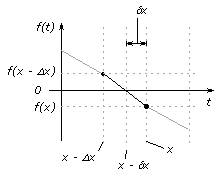
A common scenario, where a data signal function f(t) intersects a reference value (zero in this case) between time steps, is shown below:

Determination of a Linearly Interpolated Point
Assuming a linear segment between time steps t = x – Dx and t = x, the exact time at which the function f(t) crosses zero would be at t = x – Dx. Referring to the above figure, the interpolated time dx can then be calculated using a simple linear ratio as follows:
![]()
Of course, the reference signal may be a value other than zero, or possibly even a dynamic function itself. In the latter case, a difference function such as:
![]()
could be used for comparison with a constant, zero reference.
The propagation of an Interpolated Time Tag dx through a control system will normally occur within a single time step. Depending on the individual control functions present, dx may be passed through the system unaltered, or it may be modified or even ignored. Indeed, there may be several distinct interpolated times propagating along various control signal paths each time step – and these quantities could possibly interact with one another.
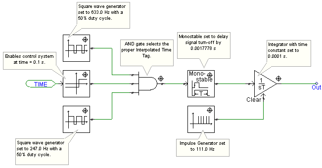
The following example illustrates what goes on during a single time step in a fully interpolated control system:

Example Interpolated Control System

Control Diagrams for Above Circuit