In the Wound Rotor Induction Machine, the rotor terminals are accessible to the user, and can be connected to an external resistance or an electrical circuit. In addition to the stator and rotor windings, there is a provision in the model to include up to three additional windings to model the effects of rotor bars (if any).
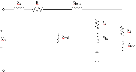
The d-axis equivalent circuit for the wound rotor induction machine with one squirrel cage in effect is shown in figure 7-4. This is derived in a manner similar to that for the synchronous machine. Similar equivalent circuits are applicable to the q axis as well as to the squirrel cage machine.

Figure 7-4 - d-axis Equivalent Circuit
NOTE: All reactance and resistance values are those referred to the stator.
Where,
|
R1= |
Stator resistance |
|
R2= |
wound rotor resistance |
|
R3= |
first cage resistance |
|
Xa= |
Stator leakage reactance |
|
Xkd1= |
wound rotor leakage reactance |
|
Xkd2= |
first cage leakage reactance |
|
Xmd= |
Magnetizing reactance |
|
Xkd12= |
Mutual inductance - Wound rotor - first cage |