Adding a Cable Cross-Section Component
Editing Cross-Section Parameters
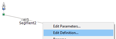
To invoke the editor, right-click over the Cable Configuration component (without selecting it) and select Edit Definition… (or double-click) as shown below:
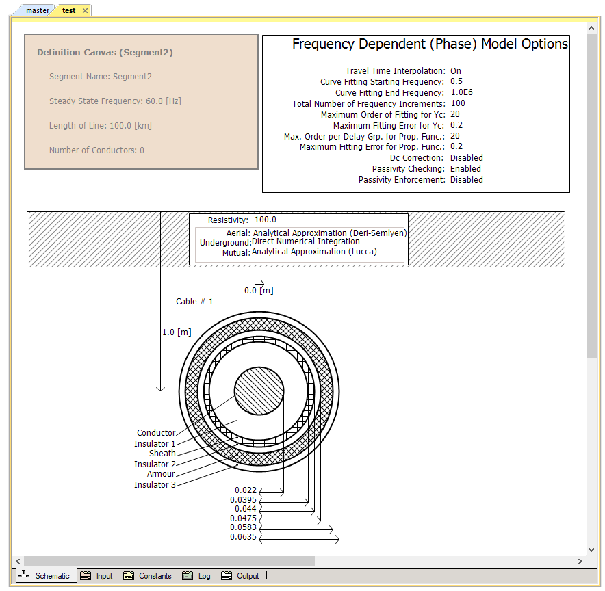
In either case, the editor will then open within the main window. As shown below, the default view is the Editor section, where the cable system is graphically defined.
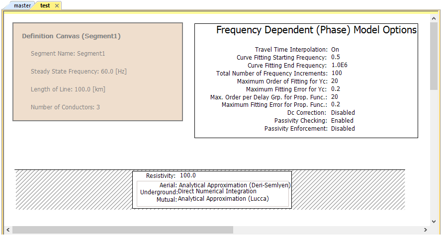
By default, the Editor section will contain three graphical objects:
Definition Canvas (<Definition Name>): Located in the top-left corner, this object simply displays what has been entered into the corresponding Cable Configuration dialog. This object is for display only and cannot be modified from inside the editor.
Frequency Dependent (Phase) Model Options: This component represents the transmission line model being used, and by default is the Frequency Dependent (Phase) model component. The parameters of this component may be edited by either a left double-click on the component (or right-click and select Edit Parameters...) to bring up the corresponding dialog window.
Entry of Ground Data: This component, usually located near the bottom of the Editor window, represents the transmission line ground return path. The parameters of this component may be edited by either a left double-click on the component (or right-click and select Edit Parameters...) to bring up the corresponding dialog window.
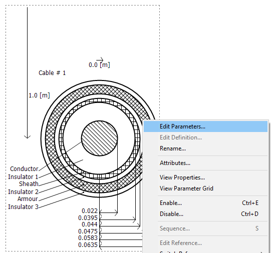
A fourth object required is the definition of the cable itself. This definition is a geometrical cross-section of the cable called a Cable Cross-Section. The user must add this manually.
|
|
|
Cable Cross-Section Component |
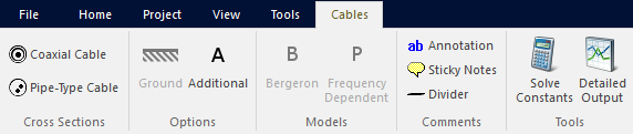
Cable Cross-Section components can be added to the editor in a couple different ways. The easiest and most straightforward way is to use the ribbon control bar. Simply select one of the available cross-sections and place it on the Schematic canvas. See Adding Components to a Project for more details.
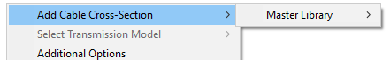
Another way is to use the context menu. On the Schematic tab, move the mouse pointer over a blank area of the window. Right-click and select Add Cable Cross-Section. A sub-menu will appear containing a list of all loaded library projects. Each of these will contain a list of all cable components available in that particular library. Select a cable and it will be automatically added.
You can also copy and paste cable components directly from any library project. Open the library in Schematic view. Select a cable cross-section, then right-click on the component and select Copy (or press Ctrl + c). Open the Editor (tab), right-click over a blank area and select Paste (or press Ctrl + v).
When finished, you should have something similar to that shown below:
NOTE: The location of the Cable Cross-Section component does not affect the results. However, the cross-section (or cross-sections) should be positioned to allow for ease in readability. That is, directly below the Ground Plane component.
Multiple cables may be added to a single configuration. Just remember to ensure that the cables are numbered properly, and that the xy-positions of the new cross-sections in the corridor are adjusted. Also, any conductors added by the additional cables must be reflected in the corresponding Cable Interface components.
Cable cross-section parameters can be edited through the corresponding cross-section parameters dialog window. Right-click over the cross-section component (without selecting it) and select Edit Parameters... to access this dialog. See Editing Component or Module Parameters for more details.