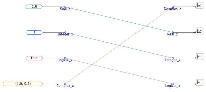
Virtual control wires can be used to provide a visual 'virtual connection' between two or more Data Label components of the same name within a specific module. Virtual control wires appear as a solid line, which runs directly between corresponding Data Labels as shown below:
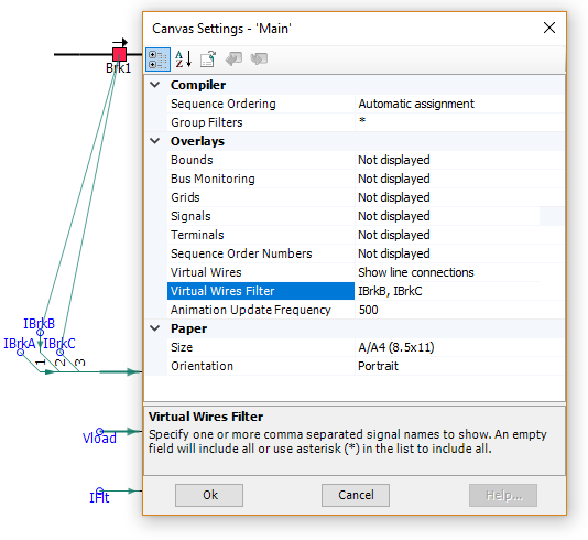
To enable this feature, right-click on a blank part of the module canvas and select Canvas Settings... to bring up the Canvas Settings dialog. Set the Virtual Wires option to Show line connections.
NOTE: Virtual wires are purely visual, that is you cannot use them as physical connections for data sources or sinks. You must compile the case first before you can view the virtual control wires.
You can filter the display of virtual wires based on signal name. This is useful in cases where there is an unruly amount of data connections, making it difficult to sort and find the signals you are interested in. Filter the virtual wires display by simply adding the names of the signals you want to see, comma separated, into the Virtual Wires Filter option in the Canvas Settings dialog. For example in the image below, the filter is being used to display only the signals IBrkB and IBrkC.
The colour of the virtual control wire indicates the data type of control signal is connecting. The colour legend is provided below:
REAL
INTEGER
LOGICAL
COMPLEX