Expression statements are a very important aspect of component design, as they provide flexibility in both the appearance and functionality of a component definition, based on instance.
The purpose of expression statements is to provide logical control over whether a parameter field, graphic object, text label or port connection is enabled, disabled, visible or invisible. Expression statements may even be used within component script segments, as a means to control the preformatting of scripted code.
Expression statements normally contain a variety of operators, in combination with condition values, which are normally based on the value of choice fields. Through expression statements, the functionality and appearance of a component becomes flexible based on instance, controllable by the user of the component.
As there is generally no standard format for an expression statement, it is best to simply start with a collection of examples.
EXAMPLE 1:
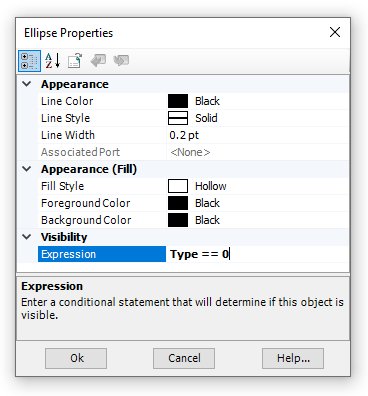
A component designer wants to change the appearance of a component graphic, according to user-selected parameter input. The component graphic is to be either an ellipse or a rectangle, depending on a choice field whose Symbol property is named Type. The choice field specifies two choices: Ellipse, which is given the integer value 0, and Rectangle, which is given the integer value 1.
In the component Parameters section, the designer adds a single choice field and configures it as described:
In the component Graphic section, the designer draws a simple ellipse and a simple rectangle:
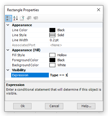
In the properties dialog for the graphic objects, the following text is added to the respective Expression properties:
|
|
Ellipse Properties |
Rectangle Properties |
If a user selects Ellipse in the choice list, only the ellipse object will appear in the component graphic. If Rectangle is chosen, only the rectangle will appear. These two unique expression statements create two unique, graphical transparencies in the component Graphic section.
Expression statements are not limited to a single, simple logical truth. It is possible to use several logical operators in a single expression statement. For example, say there is another choice field added to the component in the above example, whose Symbol property is named Type2. Now assume that in order for the ellipse object to be visible on the component graphic, it is required that Type2 have a value of 3 (in addition to Type having a value of 0). Then the following expression statement would need to appear in Expression property of the ellipse object:
(Type == 0) && (Type2 == 3)
The above states: If Type equals 0 and Type2 equals 3, then make the ellipse visible.
Operators and functions may also be included in expression statements. For example, the following statement is also valid:
(Type + Type2 == 3)
The above states: If the sum of Type and Type2 equals 3, then make the ellipse visible.
NOTE: Care must be exercised when using the divide (/) function, as a divide by zero error can occur.
PSCAD comes complete with a variety of mathematical functions and standard operators that can be used in various places about the application environment. They are mainly within expression statements.
An inherent set of mathematical functions is available. The table below lists all of the intrinsic mathematical functions available in while scripting in PSCAD.
Function |
Description |
CEIL(x) |
Rounds fraction to next upper integer |
FLOOR(x) |
Rounds fraction to next lower integer |
ROUND(x) |
Adds 0.5 to a REAL value and then performs an INT function (i.e. ROUND(X) = INT(X+0.5)). Do not use with negative numbers |
TRUNC(x) |
Rounds x toward zero, returning the nearest integral value that is not larger in magnitude than x. |
FRAC(x) |
Removes integer part of REAL value (left side of decimal) |
REAL(x) |
Real part of complex number |
IMAG(x) |
Imaginary part of complex number |
ABS(x) |
Absolute value |
ARG(x) |
Returns the phase angle (or angular component) of the complex number x, expressed in radians. |
NORM(x) |
Norm of complex number (x2 + y2) |
SIN(x) |
Sine function |
COS(x) |
Cosine function |
TAN(x) |
Tangent function |
ASIN(x) |
Inverse sine function |
ACOS(x) |
Inverse cosine function |
ATAN(x) |
Inverse tangent function |
SINH(x) |
Hyperbolic sine function |
COSH(x) |
Hyperbolic cosine function |
TANH(x) |
Hyperbolic tangent function |
SQRT(x) |
Square root |
LOG(x) |
Natural logarithm |
LOG10(x) |
Base 10 logarithm |
EXP(x) |
Exponential |
RAND(x) |
Random value between 0 and x |
P2RX(m,q) |
Polar to rectangular conversion (q in degrees) |
P2RY(m,q) |
Polar to rectangular conversion (q in degrees) |
R2PM(x,y) |
Rectangular to polar conversion |
R2PA(x,y) |
Rectangular to polar conversion |
INT(x) |
Removes fractional part of REAL value (right side of decimal) |
NINT(x) |
Returns the nearest integer to the argument |
MIN(...) |
Returns the minimum value from the list of real numbers provided. |
MAX(...) |
Returns the maximum value from the list of real numbers provided. |
Listed below are functions to
Function |
Description |
select(x,...) |
Selects the x option in the argument list and returns the corresponding value, where x is an INTEGER and '...' is a list of values. |
getchoicetext(x,y) |
Selects TEXT y of a choice parameter based on an INTEGER x provided. |
EXAMPLE 2:
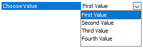
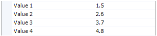
A component designer wants to display one of multiple parameter values (Symbols value_1, value_2, value_3 and value_4), depending a user-selected choice parameter value (Symbol value_choice), in a text label in component graphic.
|
|
|
Choice Parameter |
Value Parameters |
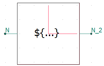
Component Graphic |
In the text label, the designer enters the following expression statement directly in the text label Text property:
${select(value_choice, value_1, value_2, value_3, value_4)}
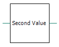
The text label will display the value currently entered in the parameter corresponding to the value of the choice parameter. For example, if the choice parameter Choose Value (Symbol value_choice) is selected as Second Value, the value of parameter Value 2 (Symbol value_2) will be displayed (2.6).
The select() function may also be used in the component script. For example, say the designer of the component in EXAMPLE 2 above, wants to define the output, real port N_2, to be the product of the input, real port N and the value of one of the Value parameters, depending on the choice parameter Choose Value (Symbol value_choice). A statement would appear as follows in the Fortran segment script of the component:
! ! Define port N_2 depending on N and parameter settings: ! $N_2 = $N * ${select(value_choice, value_1, value_2, value_3, value_4)} ! |
EXAMPLE 3:
Say the component designer in EXAMPLE 2 above, now decides that instead of displaying the actual value of the Value parameters, the description of the choice parameter value (Symbol value_choice), is to be displayed in a text label in the component graphic.
|
|
|
Choice Parameter |
Component Graphic |
Graphical Display When Choose Value is Selected as Second Value |
In the text label, the designer enters the following expression statement directly in the text label Text property:
${getChoiceText(value_choice, "value_choice")}
Listed below are the arithmetic operators available in PSCAD.
Function |
Description |
+ |
Add |
+= |
Add assign |
- |
Subtract |
-= |
Subtract assign |
* |
Multiply |
. |
Multiply |
*= |
Multiple assign |
/ |
Divide |
/= |
Divide assign |
% |
Modulo |
%= |
Modulo assign |
** |
Raise to power |
**= |
Raise to power assign |
\\ |
Parallel (xy) / (x +y) |
² |
Square |
³ |
Cube |
Listed below are the logical operators available in PSCAD.
NOTE: Logical expressions will return a value of 1 if true, and a value of 0 if false.
Function |
Description |
== |
Equal to |
!= |
Not equal to |
! |
Not |
~ |
Compliment |
< |
Less than |
> |
Greater than |
<= |
Less than or equal to |
>= |
Greater than or equal to |
|| |
OR |
| |
OR binary |
||= |
OR assign |
|= |
OR assign binary |
&& |
AND |
& |
AND binary |
&&= |
AND assign |
&= |
AND assign binary |
^^ |
XOR |
^ |
XOR binary |
^^= |
XOR assign |
^= |
XOR assign binary |
<< |
Left shift |
<<= |
Left shift assign |
>> |
Right shift |
>>= |
Right shift assign |
EXAMPLE 4:
Logical operators can appear in many different areas. The following examples illustrate the various ways these operators can be used:
! ! ...with #IF, #ELSEIF, #ELSE, #ENDIF Directives ! #IF F >= 60.0 Fout = 60.0 #ENDIF ! ! ...with a Ternary Operator in the Computations ! segment ! REAL L = X == 0.0 ? Y*2.0 : Y/3 ! ! ...in the Checks segment ! ERROR Value too small : R > 0.001 ! |
The ternary operator is yet another short form method offered in definition script for representing an IF-ELSE-ENDIF type expression. It allows the user to define a variable, according to certain conditions, in a single line.
The ternary operator should appear as follows:
<Logic> ? <Value_if_True> : <Value_if_False>
<Logic> is a logical expression using logical operators. <Value_if_True> and <Value_if_False> can either be a single constant, or a mathematical expression.
NOTE: Care must be taken when designing components with ternary operators: Ensure that variables used within the ternary expression will not be disabled under otherwise valid conditions. In other words, unrelated logic may disable one or more of the variables used within the ternary expression, which may render the ternary result invalid.
EXAMPLE 5:
A user wants to define a REAL variable X in the Computations segment of a component definition. The value of X is to be 1.0 if an input parameter N is 2 or 3, and defined by a mathematical expression otherwise.
The following code should appear in the Computations segment:
REAL X = (N==2 || N==3) ? 1.0 : SQRT(2)*V |
Where V is a predefined constant.
EXAMPLE 6:
A user wants to define a REAL variable Torq in the Computations segment of a component definition. The value of Torq is defined by a mathematical expression, where one element of this expression varies according to a condition. This can be accomplished by using the ternary operator as follows:
REAL Torq = (X > 1 ? 0.0 : Tm) + Te*100 |
Where X, Tm and Te are predefined constants.