The Overhead Line Interface component is used to identify and provide the number of electrical connections at each end of a transmission corridor (right of way) in air. This component must be used along with the Overhead Line Configuration component as described in Constructing Overhead Line Systems.
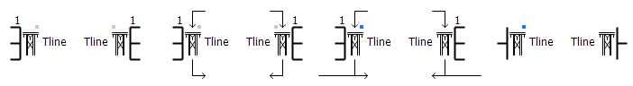
NOTE: Electrical connections to the interface are numbered from top to bottom, 1 being at the top.
More: |
Name (Same as Configuration) |
|
Text |
|
Enter a name for the overhead line. This name must match both the corresponding Overhead Line Configuration component, as well as the second interface component |
||||||
|
|
|
|
|
||||||
Segment End Specification |
|
Choice |
|
Select automatic, sending or receiving.
Select sending or receiving to designate the interface as either/or. Note that if one interface is specified as sending, the other must be specified as receiving or vice versa. Or, both can be selected as automatic.
This is very important when working with mutually coupled systems in remote-end mode, in order to ensure proper node/subsystem mapping and EMTDC runtime results. Specifying ends is not necessary for non-mutually coupled systems, but is recommended nonetheless.
Graphical indicators are provided as follows:
|
||||||
|
|
|
|
|
||||||
Number of Equivalent Conductors |
|
Choice |
|
Enter the total number of equivalent conductors for this right of way (maximum 20). A single equivalent conductor includes all bundled conductors within it. |
||||||
|
|
|
|
|
||||||
Graphics Display |
|
Choice |
|
Select 3 phase view or Single Line view |
||||||
|
|
|
|
|
||||||
Sending Signal Dimension |
|
INTEGER |
Literal |
Enter the dimension of the optional, non-electrical signal to be transferred to the other end of the line. See Control Signal Carrier for more details. |
||||||
|
|
|
|
|
||||||
Receiving Signal Dimension |
|
INTEGER |
Literal |
Enter the dimension of the optional, non-electrical signal to be received from the other end of the line. See Control Signal Carrier for more details. |
||||||
|
|
|
|
|
||||||
Receiving Signal Default Entry |
|
Choice |
|
Select Direct Entry or Signal Input.
When Direct Entry is selected, use the Receiving Signal Default Value parameter to enter the actual value. An external connection on the component will appear for connecting a Signal Input.
Note that if the receiving signal default is not set, the value will always be 0.0 at simulation time = 0.0.
This parameter is enabled when Receiving Signal Dimension is greater than 0. |
||||||
|
|
|
|
|
||||||
Receiving Signal Default Value |
|
REAL |
Literal |
The default value for the receiving signal at simulation time = 0.0.
This parameter is enabled when Receiving Signal Dimension is greater than 0. |
Inter-Application ConfigurationInter-Application Configuration
End Type |
|
Text |
|
Select Server, Client or None.
This option should be set to Server or Client for inter-application simulations, set to None if both ends of the line are in a single instance of PSCAD. |


