
This component models a saturable reactor. It can be used in either single-phase or single-line, 3-phase circuits.
Data can be entered as a table of pairs in the form of Irms-Vrms , i-l or H-B to a maximum of 10 points of data. If more data points are available, then an external file can be used with a maximum limit of 100 data points. Successive data points should increase in magnitude. If successive data points do not correspond to a continuously decreasing rate of change, offending data points will be removed and the user will be informed through a warning message.
The following conversion formulae are used to compute the corresponding actual values, based on the input base and per-unit parameter data:
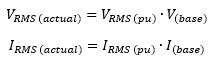
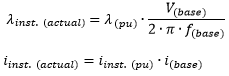
and,
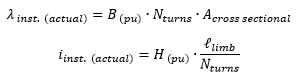
More: |
Reactor Name |
|
Text |
|
Name to identify the reactor component. |
|
|
|
|
|
Data Input Format |
|
Choice |
|
Select I - V (rms), i - lamda (inst.) or H - B (inst.) |
|
|
|
|
|
Data Input Source |
|
Choice |
|
Select Table or Data file. See Input Data File Format for more details on data file format. |
|
|
|
|
|
Datafile Name |
|
Text |
|
Enter the name of the data file, or the full path name to the data file, depending on the setting of the Pathname to datafile given as parameter.
This parameter is enabled when Data Input Source | Data file is selected. |
|
|
|
|
|
Pathname toDatafile Given as |
|
Choice |
|
Select Relative Path or Absolute Path.
This parameter is enabled when Data Input Source | Data file is selected. |
|
|
|
|
|
Number of Data Points |
Choice |
|
Select 2 to 10. This parameter is enabled only if Data Input Source | Table is selected. |
|
|
|
|
|
|
Base Voltage (per phase) |
REAL |
Constant |
Enter the base voltage for per-untizing [kV, RMS, per-phase] |
|
Base Current (per phase) |
REAL |
Constant |
Enter the base current for per-untizing [kA, RMS, per-phase] |
|
Base Frequency |
REAL |
Constant |
Enter the base frequency [Hz] |
|
Number of Turns |
INTEGER |
Constant |
Enter the number of turns. This parameter is enabled when Data Input Format | B - H is selected. |
|
Cross-Sectional Area of Magnetic Limb |
REAL |
Constant |
Enter the cross-sectional area of the magnetic limb. This parameter is enabled when Data Input Format | B - H is selected. |
|
Length of Magnetic Path |
REAL |
Literal |
Enter the length of the magnetic path. This parameter is enabled when Data Input Format | B - H is selected. |
Core Characteristic TableCore Characteristic Table
NOTE: The following is visible only if Data Input Format | I - V (rms) is selected.
Point # - RMS Current |
|
REAL |
Constant |
RMS current coordinates [pu] |
|
|
|
|
|
Point # - RMS Voltage |
|
REAL |
Constant |
RMS voltage coordinates [pu] |
NOTE: The following is visible only if Data Input Format | i - lamda (inst.) is selected.
Point # - Current |
|
REAL |
Constant |
Instantaneous current coordinates [pu] |
|
|
|
|
|
Point # - Flux Linkage |
|
REAL |
Constant |
Instantaneous flux linkage coordinates [pu] |
NOTE: The following is visible only if Data Input Format | B - H is selected.
Point # - Flux Density |
|
REAL |
Constant |
Flux density coordinates [T] |
|
|
|
|
|
Point # - MMF |
|
REAL |
Constant |
Magneto-motive force coordinates [A/m] |
Internal OutputsInternal Outputs
Lamda [kW-turns] |
|
REAL |
Output |
The calculated lamda [kW-turns] |
|
|
|
|
|
Winding Current [kA] |
|
REAL |
Output |
The winding current [kA] |