
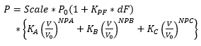
This component models the load characteristics as a function of voltage magnitude and frequency. The expression of the characteristics is as follows:
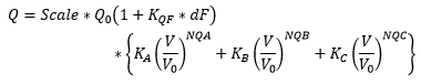
And,
Where,
P = |
Equivalent load real power |
Q = |
Equivalent load reactive power |
Scale = |
Load scaling factor |
P0 = |
Real power at specified condition (Rated or Initial terminal) |
Q0 = |
Reactive power at specified condition (Rated or Initial terminal) |
|
Load voltage |
|
Voltage at specified condition (Rated or Initial terminal) |
KPF = |
dP/dF Frequency index for real power |
KQF = |
dQ/dF Frequency index for reactive power |
KA = |
Portion of the load specified by the first term |
NPA = |
dP/dV voltage index for real power in the first term |
NQA = |
dQ/dV voltage index for reactive power in the first term |
KB = |
Portion of the load specified by the second term |
NPB = |
dP/dV voltage index for real power in the second term |
NQB = |
dQ/dV voltage index for reactive power in the second term |
KC = |
Portion of the load specified by the third term |
NPC = |
dP/dV voltage index for real power in the third term |
NQC = |
dQ/dV voltage index for reactive power in the third term |
NOTE: dQ, dP, dV and dF are in all per-unit quantities
If this component is used in single-phase mode, every half cycle (at the appropriate voltage zero), the shunt resistor/inductor/capacitor is updated to reflect the nonlinear load effect as a function of RMS voltage and frequency.
If used in a 3-phase, single-line mode, the RLC values of all phases are changed when the voltage of any one of the phases goes through a zero crossing.
The load remains in constant impedance form until the user specified number of cycles of the fundamental frequency is passed. The nonlinear characteristic is effective within ±20% of the specified RMS voltage and ±DF% of the rated frequency (DF is defined as minimum of 10, 90/KPF and 90/KQF). Outside this range, the load reverts to constant impedance.
Quick Reference for Index Parameter Selection |
||||
dP/dV |
dQ/dV |
dP/dF |
dQ/dF |
|
| Constant Resistance | 2 |
|
0 |
|
| Constant Reactance |
|
2 |
|
0 |
| Constant Inductance |
|
2 |
|
-1 |
| Constant Capacitance |
|
2 |
|
1 |
| Constant Real Current | 1 |
|
0 |
|
| Constant Reactive Current |
|
1 |
|
0 |
| Constant Real Power | 0 |
|
0 |
|
| Constant Reactive Power |
|
0 |
|
0 |
IMPORTANT NOTE: The initial values of R, L and C are computed based on the rated conditions supplied by the user. These values are kept constant until the specified number of cycles of the fundamental frequency has passed.
More: |
See Reference [3] for more details on static load models and typical values for NP, NQ, KPF and KQF. |
Name |
Text |
Optional text parameter for identification of the component. |
||
Rated Real Power per Phase |
|
REAL |
Constant |
Real steady-state 1-phase power into load [MW]. |
|
|
|
|
|
Rated Reactive Power (+inductive) per Phase |
|
REAL |
Constant |
Steady state reactive power into load, where inductive load is entered as +ve in value (capacitive as -ve) [MVAr]. |
|
|
|
|
|
Rated Load Voltage (RMS L-G) |
|
REAL |
Constant |
Expected steady state line-to-ground RMS volts across the load [kV]. |
|
|
|
|
|
Initial Terminal Voltage |
|
REAL |
Constant |
Initial terminal voltage [pu]. |
|
|
|
|
|
PQ Defined at |
|
Choice |
|
Select Rated Voltage or Initial Terminal Voltage. |
|
|
|
|
|
Number of Parts in the Composite Load |
|
Choice |
|
Select 1, 2 or 3. |
|
|
|
|
|
Fundamental Frequency |
REAL |
Constant |
System fundamental frequency [Hz]. |
|
|
|
|
|
|
Scaling Factor |
|
REAL |
Variable |
Enter a scaling factor for the load. Scaling factor should be positive. |
|
|
|
|
|
Number of Cycles before Load Release |
|
REAL |
Constant |
Enter the number of cycles of the rated frequency during which time load is held constant. |
|
|
|
|
|
Display Details? |
Choice |
Select Yes or No.
Selecting Yes will display Rated Real Power per Phase and Rated Reactive Power on the component graphic. |
||
|
|
|
|
|
Frequency Index for P (dP/dF) |
REAL |
Constant |
Frequency index for real power. |
|
Frequency Index for Q (dQ/dF) |
REAL |
Constant |
Frequency index for reactive power. |
|
|
|
|
|
|
Voltage Index for P (dP/dV) - Part A |
|
REAL |
Constant |
Voltage index for real power. |
|
|
|
|
|
Voltage Index for Q (dQ/dV) - Part A |
|
REAL |
Constant |
Voltage index for reactive power. |
Internal OutputsInternal Outputs
Effective Resistance per Phase |
|
REAL |
Output |
Name for effective per phase resistance [W]. |
|
|
|
|
|
Effective Inductance per Phase |
|
REAL |
Output |
Name for effective per phase inductance [H]. |
|
|
|
|
|
Effective Capacitance per Phase |
|
REAL |
Output |
Name for effective per phase capacitance [mF]. |