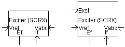
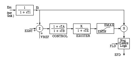
This exciter is based on an IEEE type SCRX solid state exciter. The output field voltage is varied by a control system to maintain the system voltage at Vref. Please note that this exciter model has no initialization capabilities - this means that it will respond to whatever inputs it receives regardless of the state of the machine model.
Inputs:
Vref: The reference voltage in per-unit, which the exciter acts to control.
If: The field current received from the machine in per-unit. It applies to the negative current logic. In the component input parameters, an option exists to enter a Reverse Resistance which is in effect inserted into the field circuit if negative field current attempts to flow. A large default value will prevent negative field current.
Vabc: Receives input from the Node Loop component. A Wire must connect the Vabc input to the Node Loop component.
Exst: Input to modify Vref and is suitable for connecting a power system stabilizer. This input is enabled only if the input parameter Extra Input Signal? is selected.
Outputs:
Ef: This output is the computed field voltage applied directly to synchronous machine. A Wire may be used to make the connection.
More: |
Name for Identification |
Text |
Optional text parameter for identification of the component. |
||
Rectifier Smoothing Time Constant |
|
REAL |
Constant |
T1 [s] |
|
|
|
|
|
Connected to a Node Loop With |
|
Choice |
|
Select Single Line View or 3-Phase View. |
|
|
|
|
|
Controller Lead Time Constant |
|
REAL |
Constant |
TA [s] |
|
|
|
|
|
Controller Lag Time Constant |
|
REAL |
Constant |
TB [s] |
|
|
|
|
|
Exciter Time Constant |
|
REAL |
Constant |
TE [s] |
|
|
|
|
|
Exciter Gain |
|
REAL |
Constant |
K [pu] |
|
|
|
|
|
Maximum Field Voltage |
|
REAL |
Constant |
EMAX [pu] |
|
|
|
|
|
Minimum Field Voltage |
|
REAL |
Constant |
EMIN [pu] |
|
|
|
|
|
L-G Voltage Base |
|
REAL |
Constant |
[kV, RMS] |
|
|
|
|
|
Line Current Base |
|
REAL |
Constant |
[kA, RMS] |
|
|
|
|
|
Reverse Resistance |
|
REAL |
|
[W] |
|
|
|
|
|
Exciter Voltage Supply |
|
Choice |
|
Select Independent or Bus Fed. With bus fed exciters, the output field voltage varies linearly with the AC voltage |
|
|
|
|
|
4 Quadrant Operation? |
|
Choice |
|
Select Yes or No. A 4 quadrant exciter can accept or deliver reverse current. Most solid state exciters are 2 quadrant |
|
|
|
|
|
Time constants => 0-Short, 1-Normal |
|
INTEGER |
Variable |
Use the machine initialization switch here. During the initialization period (0) the exciter will use short time constants and then switch to regular time constants when the machine rotor is released. The exciter controller time constants are usually very long. Setting this to 'Short' artificially shortens these time constants to allow the system to stabilize faster |
|
|
|
|
|
Extra Input Signal? |
|
Choice |
|
Select Yes or No. Sometimes an extra signal into the voltage summation control block is desirable (such as a stabilizer signal) |