
This component channels and records the signal to which it is connected, for the purpose of display in an online display device (such as a Graph, Meter, Polymeter, etc.) or for insertion into an Output File.
Proper Usage:
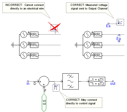
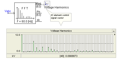
The Output Channel will accept any type of INTEGER or REAL control signal (either scalar or vector). If the signal is a vector, the Output Channel will automatically adjust itself to the signals dimension. This allows for an entire data vector to be channelled directly in to a display device with a couple of mouse clicks.
NOTE: Measured voltages and currents are by default in kV and kA respectively. If you want the output channel to output the signal in another unit, you must scale the signal using the Scale Factor parameter.
More: |
Title |
|
Text |
|
A short description describing the signal being recorded. This text will also be used for display in the corresponding graph or meter |
|
|
|
|
|
Group |
|
Text |
|
Enter the name of the Runtime Object Group, to which this component is to belong (default is blank). |
|
|
|
|
|
Use Signal Name as Title? |
|
Choice |
|
Select Yes or No.
If enabled, the output channel will assume the name of the signal, to which it is connected. The signal name is generic and is assigned upon compilation of the module. Note that if left enabled, the output channel title will continue to dynamically change with the signal name. |
|
|
|
|
|
Transfer Data? |
|
Choice |
|
Select Yes or No.
Enable or disable the transfer of plotting data between EMTDC and PSCAD. If No is selected, this output channel will not request data transfer from EMTDC. Disabling helps to reduce redundant memory usage during runtime. The data will still be saved if recording output files, although on-line plotting is disabled. |
|
|
|
|
|
Display Title on Icon? |
|
Choice |
|
Select Yes or No to display the Title directly on the component graphic. This has no effect on the display in the corresponding Control Panel interface. |
|
|
|
|
|
Scale Factor |
|
REAL |
Literal |
The input is multiplied by this value before it is recorded |
|
|
|
|
|
Unit |
|
Text |
|
Enter the unit for display on meters. This input parameter does not scale the output value |
|
|
|
|
|
Multiple Run Save |
|
Choice |
|
Select Last Run Only or All Runs.
The default selection is to save the output on Last Run Only. If you are running in non-multiple run mode, the first run itself is the last run. If you are in multiple run mode, you can save the complete data for each channel for each run by selecting the All Runs option. |
|
|
|
|
|
Is Input in Polar Form? |
|
Choice |
|
Select Yes or No.
If Yes is selected, and the input signal is an array with an even dimension (i.e. 2, 4, 6, etc.), then the Scale Factor input parameter is applied only to the odd elements of the array. This feature convenient when using Phasormeters, which require input to be in polar format.
If No is selected, the Scale Factor input parameter is applied to all elements. |
|
|
|
|
|
Default Maximum Display Limit |
|
REAL |
Literal |
Enter a value to control the maximum display limit on devices such as Meters, Polymeters and Phasormeters.
This value may also be used as a means to saving the y-axis limits on Graphs. See Synchronizing Output Channel Limits with Those of the Graph specifically for more details on this. |
|
|
|
|
|
Default Minimum Display Limit |
|
REAL |
Literal |
Enter a value to control the minimum display limit on devices such as Meters, Polymeters and Phasormeters.
This value may also be used as a means to saving the y-axis limits on Graphs. See Synchronizing Output Channel Limits with Those of the Graph specifically for more details on this. |