The multiple-run component is available to users for the purpose of performing parametric studies. Through selection of appropriate parameter and input settings, the user can adjust the number of simulations that will be executed (number of simulation runs). The output variable signals from this component can be used as input signals to other components.
The inputs and outputs of this component are:
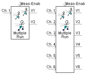
Meas-Enab: Used to enable (1) or disable (0) the channel recording. Recording will be active only when the input to this variable is 1. Thus, the user can select the time interval(s), over which the input data will be considered for processing and recording.
Ch. 1 ... Ch. 6: Input signals to be recorded.
V1, V2 ... V6: Output signals controlled by the component.
Some application examples are as follows:
The output signal values (any given output signal is constant for a given simulation run) can be used as inputs to either variable-type parameters or connection ports on any other component. If a constant-type parameter needs to be controlled, then a simulation set consisting of a master project and corresponding slave projects should be used. The master project should contain the multiple run component and slave projects should be set to start from time = 0.0. For recording the multiple run summary, the Multiple Run Additional Recording component can be used in the slave projects. Depending on the requirements, the user can select to output up to six signals (V1 to V6). However, only one of the output signal values can changed between two successive simulation runs.
The values of input signals (Ch. 1 to Ch. 6) can be saved in a multiple run output file, along with the output signals which were used for that run. Each signal can also be automatically processed for common operations (such as min and max). In addition, criteria defining an optimum run can be set, so this run will be repeated and displayed on the screen as the last run. See Measuring/Recording Signals During Multiple-Runs for more details.
More: |
Measuring/Recording Signals During Multiple-Runs Multiple Run Additional Recording Optimization and Multiple Runs |
Name for Identification |
Text |
Optional text parameter for identification of the component. |
||
Number of Signals to Control for This Multiple Run: |
|
Choice |
|
Select 1 to 6 for the number of output signals controlled. The output signals are used to vary simulation parameters during successive runs. |
|
|
|
|
|
This Multiple Run Enabled or Disabled? |
|
Choice |
|
Select Enabled or Disabled.
The multiple-run component can be disabled with this selection. When disabled, the output values will be as defined under Default Values When Disabled category page.
This option lets the user have more than one multiple-run component in a project (if different multiple-run sequences are required for a given simulation). Only a single, active multiple-run component is allowed in a project. An error is given if 2 or more multiple run components are enabled simultaneously.
This would also let the user create a snapshot with the multiple-run disabled and continue the simulation with multiple-run enabled starting from the snapshot file. |
|
|
|
|
|
# of Std Dev's for Defining min,max using the Normal Dist. (1-10): |
|
REAL |
Literal |
When using Variation Type | Random-Normal, this quantity defines the number of standard deviations to shape the distribution over the specified range. |
|
|
|
|
|
Initial Seed for Random Variations |
|
Choice |
|
Select Automatic or Specify.
If Automatic is selected, a random seed value is generated. Thus the Random-Normal outputs will not be identical when the simulation is run a second time. It would also create different seed values for different tasks if the project is used in a volley launch. |
|
|
|
|
|
Initial Seed Value |
|
Integer |
Literal |
Specify an initial seed value if Initial Seed for Random Variations | Specify is selected.
If a repeatable sequence of random numbers is desired, then the user must specify the initial seed value. The initial seed is used in random number variations for multiple runs, and is saved in the multiple run output file. If the same sequence of random numbers is desired in subsequent runs, then copy the seed value from the multiple run output file and use it to specify the initial seed.
The range for this value is 1 through 2147483647. |
|
|
|
|
|
Number of Channels to Record for Each Run |
Choice |
Select from 1 to 6. The maximum number of recording inputs is limited to 6. If more than 6 inputs recordings are required, use the Multiple-run Additional Recording component. |
||
Output File Name |
Text |
Enter a name for the multiple run output file |
||
Do you want to Identify the Optimal Run? |
Choice |
Select Yes or No.
This option enables the user to identify one out of the multiple simulations as the optimal (i.e. best or worst) case. When more than one input is being recorded, the user will need to specify the input channel (see next parameter description) to consider for the identification of the optimal run. |
||
Select Channel for Basis of Optimal Run |
Choice |
Select from 1 to 6.
The selected input will be the base for selection of optimal run. |
||
Criteria for Identification of Optimal Run? |
Choice |
Select Min or Max.
The optimal run maybe based on the minimum or the maximum value of the input signal during the recorded duration. |
||
Number of Divisions for Prob. Density Output Plots |
INTEGER |
Literal |
The multiple-run component can be used to process the recorded data to obtain additional statistical information (i.e. min, max, mean, standard deviation, probability density outputs, etc.). This parameter lets you specify how many divisions are to be used to calculate the probability density function.
Example:
Consider a case where 100 switching scenarios were simulated (using the multiple-run component). Voltages are being recorded to determine the worst-case transient overvoltage. Assume that the peak recorded overvoltage value over the 100 simulations ranged from 100 kV to 200 kV. The probability density function with 10 divisions would list you how many of the switching scenarios resulted in an overvoltage in the ranges 190-200 kV, 180 -190 kV, 100-110 kV, etc. |
NOTE: See Variation Type for more on these parameters. The parameters are enabled only if I/O Type is selected as Real.
V# Variation Type |
Choice |
Select Sequential, Random-Flat, List or Random-Normal. See Variation Type for more details. | ||
|
|
|||
V# Data Type |
Choice |
Select Real or Integer type for each corresponding variable. | ||
|
|
|||
Label for Variable # |
Text |
Enter a text label for the corresponding variable. Each multiple run variable is written to the multiple run output file for each simulation run. The first line of this file is a string defining a name for each column. | ||
|
|
|||
Value for Variable # When Disabled |
INTEGER/REAL |
Variable |
Enter a value for the corresponding variable: This will be the output value of the corresponding variable when the option: This Multiple Run Enabled or Disabled? is set to disabled. |
|
|
|
|||
Number of Runs for Variable # |
INTEGER |
Variable |
Enter the number of runs for the corresponding variable number (disabled if V# Variation Type is Sequential for the corresponding output variable). |
|
|
|
|
|
|
Start of Range for Variable # |
INTEGER/REAL |
Variable |
Enter the start of range for the corresponding variable number (disabled if V# Variation Type is List for the corresponding output variable). |
|
|
|
|
|
|
Increment for Each Run |
INTEGER/REAL |
Variable |
Enter the amount to increment each run (enabled only if V# Variation Type is Sequential is assigned for the corresponding output variable) |
|
End of Range for Variable # |
INTEGER/REAL |
Variable |
Enter the end of range for the corresponding variable number (disabled if V# Variation Type is List for the corresponding output variable) |
|
Variable # Value During Run # (List) |
INTEGER/REAL |
Variable |
Enter the value of the variable during the corresponding run (enabled only if V# Variation Type is List for the corresponding output variable) |
Channel # Data Type |
|
Choice |
|
Select Boolean, Integer or Real |
|
|
|
|
|
Auto Processing of Channel #? |
|
Choice |
|
Select None, Minimum(X), Maximum(X), Maximum(| X |) or ISE(X) [Sum(X*X)] |
|
|
|
|
|
Label for Channel # |
|
Text |
|
Each multiple run variable is written to the multiple run output file for each simulation run. The first line of this file is a test string defining a name for each column. |