(8-39)
Aerial Ground Wire Elimination
In many cases, it is possible to reduce the transmission system matrix dimension by eliminating individual conductors. This process can help to increase the solution speed, without greatly affecting the accuracy of results. Conductor elimination is performed within the LCP in the following areas:
Optional elimination of aerial ground wires in overhead transmission lines
Optional elimination of conducting layers in single-core cables.
Reduction of sub-conductor bundles into their equivalent single conductor form (not optional).
The Kron matrix reduction technique is used in all areas.
The Kron reduction technique can be illustrated with the following simple example of reducing the system Z matrix by eliminating aerial ground wires:
|
|
(8-39) |
The 'g' and 'c' subscripts represent the conductor and ground groups respectively. In the case of eliminating ground wires, it is assumed that Vg = 0.0, which leads to:
|
|
(8-40) |
Where,
|
|
(8-41) |
A similar procedure is also applied to the inverse shunt conductance matrix Y-1.
In overhead transmission systems, ground wires are usually strung from tower to tower, above the main phase conductors. The ground wires are bonded to ground at each tower, which normally span approximately 350 m. When considering line parameters below about 350 kHz, it is safe to assume that ground potential is uniform throughout the ground wire span [24]. In other words, the ground wires may be eliminated from the matrix equations, thereby reducing their dimension and speeding up the solving process.
It is important to note that the elimination of ground wires from a transmission line is not the same as having no ground wires at all. The mere presence of the ground wires, even if they are eliminated, affects the remaining system Y and Z matrices.
When defining underground cable systems, an option is provided to allow for mathematical elimination of specified conducting layers in a cable. In a practical sense, this feature is useful in situations where, for example, the outer insulating material on the cable is semi-permeable, thereby permitting contact between the return medium (i.e. sea water or soil) and the outer conducting layer. In this situation, the outer conducting layer effectively becomes part of the return medium, although the overall radius of the cable, which is used in the calculation of earth return impedance, remains unchanged.
The bundling together of two or more sub-conductors to form a single phase conductor is common practice in overhead transmission line design. The sub-conductors are normally held together with spacers in a symmetrical, equidistant pattern (asymmetrical positioning is also used).

Figure 8-13: Orientations of Symmetrical Bundled Conductors
Based on the assumption that the phase current is divided evenly amongst the sub-conductors, and that each carries the same phase voltage, the conductor bundle may be reduced to a single, equivalent phase conductor. The Line Constants Program performs this equivalency by using the Kron reduction technique as described earlier.
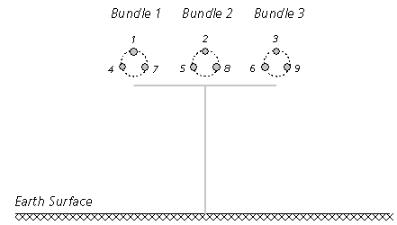
There are two avenues for entering bundled conductor data; symmetrical and asymmetrical. If the bundle is symmetrical (as shown in Figure 8-13), then simple trigonometric techniques are used to calculate the individual XY coordinates of each sub-conductor, given the sub-conductor spacing dsc and the number of sub-conductors per bundle N. If the bundle is asymmetrical, then the XY coordinates of each sub-conductor must be entered directly.

Figure 8-14: Cross-Section of a 3-Phase Transmission System with Three Sub-Conductor Bundles
Each sub-conductor is initially considered a separate entity when the system matrices are constructed. For example, if a transmission system consists of a single three-phase circuit, where each phase conductor consists of three sub-conductors (as shown in Figure 8-14), then the resulting system matrix dimensions would be 9 x 9, as shown below for the series impedance matrix Z (where the individual matrix elements are calculated as described in the section entitled Deriving the System Y and Z in this chapter).
|
|
(8-42) |
Once the system matrices are defined, the Kron reduction procedure is invoked, which effectively reduces the system matrices down to their single-conductor, multiple phase equivalent. For example Equation 8-42 is reduced to:
|
|
(8-43) |
In the end, the effective number of conductors in this example is 3. This will need to be considered when you are externally connecting the transmission system to the greater network in PSCAD. See Constructing Overhead Lines or Constructing Underground Cables in the PSCAD Manual.