
This component models a multi-valve, full-bridge MMC with Thévenin equivalent circuits, which effectively increases the computational efficiency [42] [43].
The equivalent resistive circuit for a full-bridge cell has been derived as shown below:

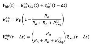
With:

The RA and RB stand for the equivalent switching resistances of the two IGBT/Diode pairs [42]. And thus, the final equivalent circuit parameters for the half-bridges are given by:
FP1, FP2, FP3, FP4: Required switching signals for the corresponding IGBT numbered as 1, 2, 3, 4.
VC: Array of capacitor voltages.
IC: Array of capacitor currents.
More: |