Equivalent Circuits for Three-Phase Fault
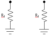
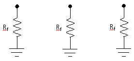
The three-phase fault component is composed of a network of two-state switching resistances (i.e. ON/OFF), where each resistor's value is determined by the type of fault being applied. The equivalent circuit is shown below:
During no-fault conditions, all of the above resistors will be given the value of what is entered in the Fault OFF Resistance input parameter (1 MW by default). When a fault is applied however, the value of Rf may change in some resistors to provide an approximation of the specified fault type.
The following diagrams describe the ON/OFF configurations of the three-phase fault component. Note that only ON resistors are shown below. Each of these resistors are given the value entered in the Fault ON Resistance input parameter (0.01 W by default).
Phase to Ground |
Phase to Phase |
Phase to Phase to Ground |
Three-Phase to Ground |
All other faults are a variation of that shown above. Also see the Knowledge Base Article.
The single-phase fault may be represented as an ideal branch when faulted, by entering 0.0 W (or a value less than the Ideal Branch Threshold) as the fault resistance. For more on ideal branches, see Ideal Branches. Simulation of an ideal short circuit can slow down the simulation, so use a non-zero value (larger than the Ideal Branch Threshold) wherever possible.
![]()