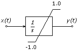
The basic building block of many control system functions is the integrator. Denoted in the Laplace Domain as 1/s, where s is the Laplace Transform variable, the integrator in PSCAD integrates an input variable to produce an integral function in the time domain. The integration function is depicted in block diagram form as shown below where x(t) is integrated to obtain y(t).
![]()
Block Diagram of the Integration Function (INTGL3)
Although there are many possible methods of integration, the method most used in EMTDC is the trapezoidal method which states:
![]()
Where,
|
|
Output integration function |
|
|
Output integration function (previous time step) |
|
|
Input function |
|
|
Input function (previous time step) |
|
|
Time step interval |
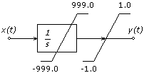
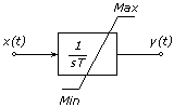
In actual control systems, the output of an integration process is usually bounded between maximum and minimum limits. In an analog system, limits are imposed by the positive and negative voltages on the supply rails to the integrator. Whereas in a digital system, output limits may be necessary for modelling purposes. The integrator may have a gain associated with it also, and its representation in block diagram form is as shown below:
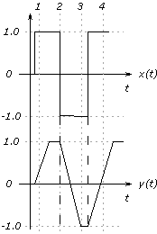
The actual application of the limits, affects the response of any model having an integrator as one of its building blocks. There are two ways in which limits may be applied: The first is when the memory function representing the output of the previous time step y(t – Dt) is not updated to y(t) when a limit is reached, or alternatively, y(t) is limited. This is known as a hard limit because it will immediately integrate off the limit when the input changes sign. This is the basis of the function INTGL3.
The second way limits can be applied to the output of an integrator is to not limit y(t) or y(t – Dt) until after y(t – Dt) is updated to y(t). In this method, the output of the integrator may integrate beyond the limit, and when the input changes sign, it will integrate back to the limit, taking time in doing so. This imposes a delay in the integrator at the limit output giving the appearance of 'sticking' or 'latching up' at the limits. An example of both types of limits is given below:
|
|
|
|
|
|
|
|
|
Effect on Limits on the Response of an Integrator
NOTE: The second type of output limiting explained above is not inherent to the INTGL3 function, however it is already programmed into the PSCAD Master Library component Integrator.
|
Author(s): |
|
|
REAL FUNCTION INTGL3(YO,TLO,THI,T,X)
|
Argument |
Type |
Dimension |
Description |
|
|
|
|
|
|
YO |
REAL |
1 |
Initial output |
|
TLO |
REAL |
1 |
Lower output limit |
|
THI |
REAL |
1 |
Upper output limit |
|
T |
REAL |
1 |
Integral time constant [s] |
|
X |
REAL |
1 |
Input signal |
This function requires the following storage allocations per call (see #STORAGE Script Directive and STORx Arrays for more details):
#STORAGE STOR:3
|
Address |
Description |
|
|
|
|
NEXC + 1 |
|
|
NEXC + 2 |
|
|
NEXC + 3 |
|