Automatic Control (3-Phase Only)
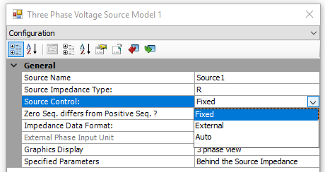
There are three source control options for the Voltage Source Model 1: Fixed, External and Auto.
F-1: Source Control Options
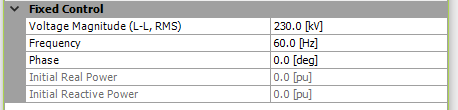
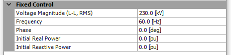
The magnitude, frequency and phase angle of the voltage source are specified internally through Source Control dialog. With this option, two different data formats can be selected to specify whether the source is Behind the Source Impedance or At the Terminal. This is controlled directly via the Specified Parameters input parameter shown below.
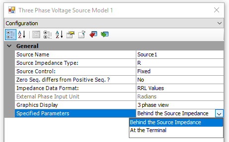
F-2: Control Parameters
Fixed control related input parameters in the Source Control dialog become enabled or disabled, depending on this selection:
|
|
|
|
F-3: Behind the Source Impedance |
F-4: At the Terminal |
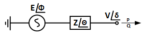
F-5: Equivalent Source and Impedance
When this option is selected, the source parameters are entered directly as Frequency (f), voltage of the source behind the impedance (E), and the angle of the source behind the impedance (φ) as shown in F-3 and F-5. The impedance (defined by Z and θ) is derived from the source impedance parameters specified by the user in the Internal Impedance dialog.
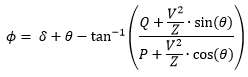
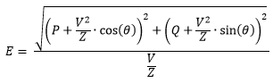
When this option is selected, the terminal parameters are entered directly (i.e. frequency (f), terminal voltage (V), terminal phase angle (δ), terminal output active (P) and reactive (Q) power) as shown in F-4 and F-5. These quantities are used to determine the voltage magnitude (E) and phase angle (φ) behind the impedance, and the angle of the source behind the impedance (E-1) and (E-2).
|
|
(E-1) |
|
|
(E-2) |
With this option, the voltage magnitude, frequency and the phase values of the source behind the impedance can be controlled externally as shown in F-6. The external values can be controlled manually by connecting a slider, or automatically through a control system output for dynamic adjustment. T-1 summarizes the external input signal units.
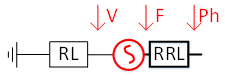
F-6: Voltage Source External Control
|
External Input Port |
Unit |
|
V |
kV, L-L, RMS |
|
F |
Hz |
|
Ph |
Deg or Rad ( depending on the External Phase Input Unit setting in the Configuration dialog.) |
T-1: External Input Signal Units
With this option, the voltage magnitude can be adjusted automatically to regulate the voltage at a selected bus and/or adjust the source phase angle internally to regulate the real power leaving the source. F-7 shows how the source is connected to allow automatic voltage control.
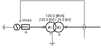
F-7: Automatic Voltage and Power Control
F-8 illustrates the voltage control block diagram, where T1 is the controller time constant and T2 is the measurement time constant, as highlighted in F-9. VA, VB and VC are the instantaneous line to ground voltage (kV) measured at a selected bus.
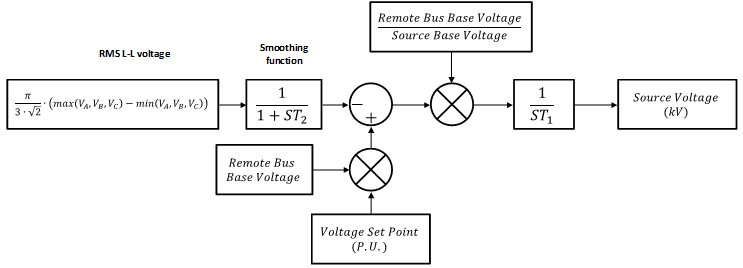
F-8: Automatic Voltage Control Configuration
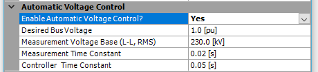
F-9: Voltage Control Input Parameter Time Constants T1 and T2
F-10 illustrates the power control block diagram where T1 is the controller time constant and T2 is the measurement time constant as highlighted in F-11. VA, VB and VC are the instantaneous line to ground voltage (kV) measured at voltage source terminal; IA, IB and IC are the instantaneous current (kA) measured leaving the terminal.
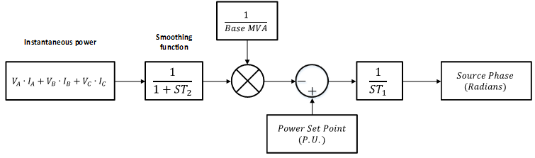
F-10: Automatic Power Control Configuration

F-11: Power Control Input Parameter Time Constants T1 and T2