The Wound Rotor Induction Machine can be operated in either 'speed control' or 'torque control' modes.
Normally, the machine is started in speed control mode with the W input set to rated per-unit speed (say 0.98) and then switched over to torque control after the initial transients of the machine die out (i.e. reaches steady-state). This component may also be used with the Multi-Mass Torsional Shaft Interface.
For more details on basic machine simulation theory, see Introduction to Machines.
|
More: |
NOTE: The Base Impedance on the stator side is (Rated Voltage (L-L))2/(Rated Power).
|
Motor Name |
|
Text |
|
Just an identifier. A name should be entered here to avoid compilation warnings. |
|
|
|
|
|
|
|
Rated Power |
|
REAL |
Constant |
Enter the power rating of the machine [MVA]. See Note. |
|
|
|
|
|
|
|
Rated Voltage (L-L) |
|
REAL |
Constant |
Enter the rated line-to-line terminal voltage [kV]. See Note. |
|
|
|
|
|
|
|
Base Angular Frequency |
|
REAL |
Constant |
Enter the machine base angular frequency [rad/s] |
|
|
|
|
|
|
|
Stator / Rotor Turns Ratio |
|
REAL |
Constant |
Enter the stator / rotor turns ratio obtained from an open circuit test. |
|
|
|
|
|
|
|
Angular Moment of Inertia (J=2H) |
|
REAL |
Constant |
This is the total inertia of all masses rotating on the machine shaft (including mechanical loads). If you are provided with the value of the Inertia Constant (H), multiply the value by 2 to obtain the value of J in per unit. [s] or [MWs/MVA]. |
|
|
|
|
|
|
|
Mechanical Damping |
|
REAL |
Constant |
Enter a value for mechanical damping to compensate for friction and windage loss [pu] |
|
|
|
|
|
|
|
Graphics Display |
|
Choice |
|
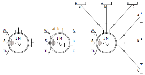
Select 3-Phase View, Single Line View or Open Terminals. |
|
External Connection to Rotor |
|
Choice |
|
Select Yes or No to enable or disable external rotor connections |
|
|
|
|
|
|
|
Multi-mass Interface |
|
Choice |
|
Select Enable or Disable. See Interfacing to the Multi-Mass Torsional Shaft for more details |
|
|
|
|
|
|
|
Stator Winding Neutral Grounded |
|
Choice |
|
Select Yes or No. If No is selected, the neutral point will become available for external grounding connection. |
|
|
|
|
|
|
|
Rotor Squirrel Cages Exist |
|
Choice |
|
Select Yes or No. A wound rotor machine with its rotor winding shorted (External Connection to Rotor - No and with Rotor Squirrel Cages Exist - No), is equivalent to a squirrel cage machine (i.e. single cage machine). |
|
|
|
|
|
|
|
Number of Rotor Squirrel Cages |
|
Choice |
|
Select from 1 to 3 rotor squirrel cages. In addition to the wound rotor, the effects of any 'cages' in the rotor can be accounted for in this model. This input is only enabled if Rotor Squirrel Cages Exist is selected |
|
|
|
|
|
|
|
Mutual Saturation |
|
Choice |
|
Select Enabled or Disabled. Models the saturation on the main magnetic paths. See Magnetizing Saturation Curve for more details |
|
|
|
|
|
|
|
Leakage Saturation |
|
Choice |
|
Select Disabled, Enabled on Stator or Enabled on Both Stator and Wound Rotor. Models the saturation near winding slots due to conductor current. See Leakage Saturation Curve for more details |
Stator and Rotor ResistancesStator and Rotor Resistances
NOTE: The Base Impedance on the stator side is (Rated Voltage (L-L))2/(Rated Power). Once converted to pu, the impedances will have the same value irrespective of if they are referred to the stator side, or the rotor side.
|
Stator Resistance |
|
REAL |
Constant |
Enter the stator winding resistance [pu] |
|
|
|
|
|
|
|
Wound Rotor Resistance |
|
REAL |
Constant |
Enter the wound rotor winding resistance [pu] |
|
|
|
|
|
|
|
First Squirrel Cage Resistance |
|
REAL |
Constant |
Enter the 1st rotor cage resistance. This input is enabled only if Rotor Squirrel Cages exist is selected [pu] |
|
|
|
|
|
|
|
Second/Third Squirrel Cage Resistance |
|
REAL |
Constant |
Enter the 2nd / 3rd rotor cage resistance. This input is enabled only if Rotor Squirrel Cages exist is selected and Number of Rotor Squirrel Cages is 2 or 3. [pu] |
Stator and Rotor InductancesStator and Rotor Inductances
|
Magnetizing Inductance |
|
REAL |
Constant |
Enter the machine magnetizing inductance [pu] |
|
|
|
|
|
|
|
Stator Leakage Inductance |
|
REAL |
Constant |
Enter the stator leakage inductance [pu] |
|
|
|
|
|
|
|
Wound Rotor Leakage Inductance |
|
REAL |
Constant |
Enter the wound rotor leakage inductance [pu] |
|
|
|
|
|
|
|
# Cage Leakage Inductance |
|
REAL |
Constant |
Leakage inductances of the different cages. This input is enabled only if Rotor Squirrel Cages exist is selected [pu] |
|
|
|
|
|
|
|
Mutual inductance: Wound rotor - Cage # |
|
REAL |
Constant |
Enter the mutual inductance between the wound rotor and different cages. This input is enabled only if Rotor Squirrel Cages exist is selected [pu] |
|
|
|
|
|
|
|
Mutual inductance: Cage # - Cage # |
|
REAL |
Constant |
Enter the mutual inductance between the different cages. This input is enabled only if Rotor Squirrel Cages exist is selected [pu] |
Mutual Saturation Curve (I, V)Mutual Saturation Curve (I, V)
NOTE: These properties are only enabled if Mutual Saturation is set to Enabled. See Magnetizing Saturation Curve for more details on setting these properties.
|
Number of Points Available |
Choice |
Select 3-10. Number of data points available. |
||
|
|
|
|
|
|
|
Magnetizing Current Point 1 |
|
REAL |
Constant |
First current point of the magnetizing curve [pu] |
|
|
|
|
|
|
|
Magnetizing Voltage Point 1 |
|
REAL |
Constant |
First voltage point of the magnetizing curve [pu] |
|
|
|
|
|
|
|
(Current, Voltage) Point # |
|
REAL |
Constant |
Enter the remaining points for magnetizing curve of the machine [pu] |
Leakage Saturation Curve (I, V)Leakage Saturation Curve (I, V)
NOTE: These properties are only enabled if Leakage Saturation is set to Enabled. See Leakage Saturation Curve for more details on setting these properties.
|
Number of Points Available |
Choice |
Select 3-10. Number of data points available. |
||
|
|
|
|
|
|
|
Short Circuit Current Point 1 |
|
REAL |
Constant |
First current point of the leakage saturation curve [pu] |
|
|
|
|
|
|
|
Short Circuit Voltage Point 1 |
|
REAL |
Constant |
First voltage point of the leakage saturation curve [pu] |
|
|
|
|
|
|
|
(Current, Voltage) Point # |
|
REAL |
Constant |
Enter the remaining points for leakage saturation curve of the machine [pu] |
Internal Output VariablesInternal Output Variables
|
Mutual Saturation Factor (pu) |
|
REAL |
Output |
Enter a name for the machine mutual saturation factor [pu] |
|
|
|
|
|
|
|
Leakage Saturation Factor (pu) |
|
REAL |
Output |
Enter a name for the machine leakage saturation factor [pu] |
|
|
|
|
|
|
|
Mechanical Speed (pu) |
|
REAL |
Output |
Enter a name for the machine mechanical speed [pu] |
|
|
|
|
|
|
|
Electrical Torque (pu) |
|
REAL |
Output |
Enter a name for electrical torque [pu] |
|
|
|
|
|
|
|
Mechanical Torque (pu) |
|
REAL |
Output |
Enter a name for mechanical torque [pu] |
|
|
|
|
|
|
|
Rotor Position (rad) |
|
REAL |
Output |
Enter a name for the rotor position angle [rad] |