
V5 Features
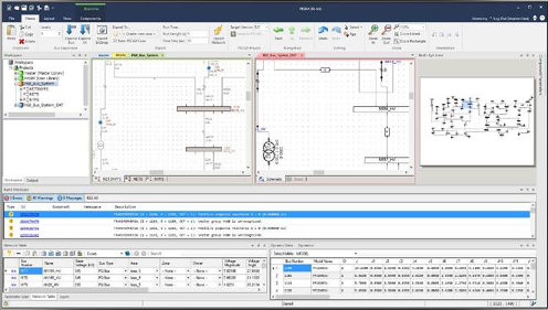
PRSIM™ (Power System Importer) - Included in Enhanced Package
The PRSIM application is available in the enhanced package and allows users to convert standard PSSE or PowerFactory network data to PSCAD with minimal time and effort.
-
Convert PSS/E and PowerFactory data files to PSCAD V5.0 and V4.6
-
Import detailed dynamic data
-
Import sequence data
-
Import location data for automatic schematic expansion
-
Form network equivalents for unexpanded segments of the network
-
Re-initialize previously generated PSCAD projects
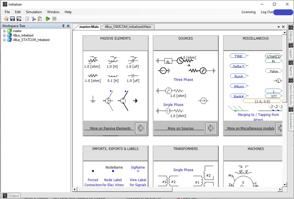
PSCAD Initializer
An Electro Magnetic Transient (EMT) program such as PSCAD simulates the behaviour of a power system network after a disturbance, such as a fault or a circuit breaker operation. During this short period, the system gradually changes from one steady-state behaviour to another.
The purpose of the PSCAD Initializer is to set up the proper power flow conditions (e.g. correct voltage and angles at buses, active, reactive power flows between buses, etc.) prior to the disturbance. This involves a solution to the power flow equations and setting up the correct parameters of generators, sources in PSCAD, etc.
Please note that the PSCAD Initializer is a separately licensed product that is included with the purchase of PSCAD.
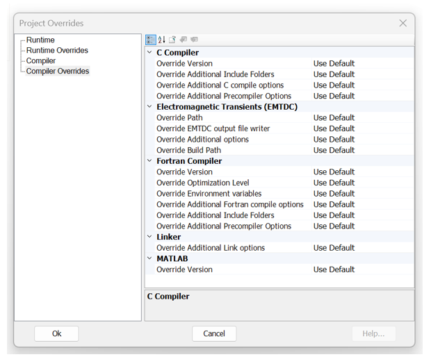
Project-Based Fortran Compiler Settings
Fortran compiler settings may now be specified on a per-project basis, as needed (as opposed to purely application-based in previous versions). By default, PSCAD will use the compiler settings specified in the Application Options | Dependencies category. However, if different compiler settings are necessary for different projects within the same workspace (for example, a PNI simulation launching multiple projects in parallel), users may now override the compiler settings set in the Application Options, on a per-project basis via a Project Settings selection.
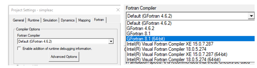
The ability to set Fortran compiler and Visual Studio configurations on a per-project basis is also now available to be overridden on a per simulation task basis. This enables you to run simulations sets in sequence that include simulation tasks using different compiler/Visual Studio combinations in different simulation sets.
Automation: Embedded Python Scripting Recording
Automation of the PSCAD application, utilizing custom-made Python language scripts, was first introduced in v4.6.1. It included commands to launch the software, load and run simulations, change parameters, and analyze data, among many others. Installed as standalone software, an automation controller library was bound to other Python scripting libraries, to achieve control over application-level features through an automation interface (part of PSCAD).
In V5, automation utilizing the Python script language is embedded directly into the software and is included with the installation of PSCAD.
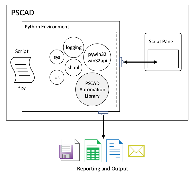
Now users can maintain their scripts from within PSCAD, using a new Script pane, from which custom scripts may be recorded, edited or launched.
Modified, Augmented Nodal Analysis (MANA) in EMTDC
Modified Augmented Nodal Analysis is an extension of nodal analysis which not only determines the circuit’s node voltages but some branch currents. This helps to mitigate some of the problems in classical nodal analysis, such as the difficulty of representing dependent sources.
Dependent source models are now included as a part of the master library. The solution automatically uses the MANA algorithm if dependent source models are included in the simulation.
KLU and GPU Sparsity Algorithms in EMTDC
KLU is a software package for solving sparse linear systems of equations that arise in circuit simulation applications. It relies on a permutation to Block Triangular Form (BTF), several methods for finding a fill-reducing ordering (variants of approximate minimum degree and nested dissection), and a sparse left-looking LU factorization algorithm to factorize each block.
EMTDC now uses the KLU algorithm for larger subsystems. The default matrix size where KLU comes into solving the equations can be set by the user.
EMTDC may also be set to utilise GPU processing power via an alternative sparse algorithm. To enable this feature, simply toggle the associated project setting.
New Master Library Models
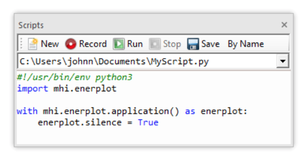
MMC Model Library:
PSCAD V5 includes a library of Modular Multilevel Converter (MMC) component models.
- Full-Bridge Cell:
This component models a multi-valve, full-bridge MMC with Thévenin equivalent circuits, which effectively increases the computational efficiency.

- Half-Bridge Cell:
This component models a multi-valve, half-bridge MMC with Thévenin equivalent circuits, which effectively increases the computational efficiency.
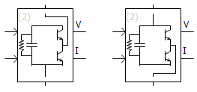
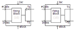
- Firing Signal Generator for MMC Full-Bridge:
This component generates firing signals to full-bridge cells based on the capacitor voltage balancing algorithm.
- Firing Signal Generator for MMC Half-Bridge:
This component generates firing signals for half-bridge cells, based on the capacitor voltage balancing algorithm.
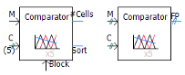
- Multi-Dimensional Comparator:
This component compares modulating waves against carrier waves generated by Carrier Signal Generator, and outputs control signals to MMC cells.
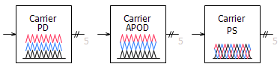
- Carrier Signal Generator:
This component generates a vector of PWM carrier signals for a specified fundamental frequency.
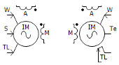
Single-Phase Induction Machine:
This component models a single-phase induction motor.
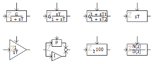
Z-Domain (Discretized) Controls:
A library of eight, commonly used controls components are included in the master library. These include: Delay, Derivative, Differential Pole, Integrator, Lead-Lag Pole, Transfer Function, PI Controller and Real Pole.
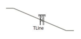
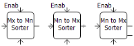
Multi-Rate (or Multi-Timestep) Transmission Line Upgrade
The transmission line configuration component has been upgraded to support multi-rate, parallel network interface (PNI) simulations (i.e. different simulation timesteps at each of its ends). There are no additional parameter settings to configure. Simply connect the PNI simulation as you normally would and run.
Note that at the time of release, multi-rate functionality is only available when using foreign ends. In other words, only PNI simulations that are run from within a single instance of PSCAD may make use of multi-rate (PNI simulations between multiple instances of PSCAD, using alien ends are not supported). The only other limitation is that the transmission line model being used must be selected as the Bergeron model.
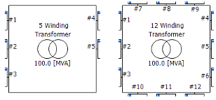
1-Phase, Multi-Winding (5-12), Transformer:
This component models a single-phase, ideal transformer that can be configured to model from 5-12 windings. Options are provided to enable a simple saturation model on a user-selected winding, as well as for adding a tap changer.
Single-Phase PI Section
A new component definition called pi_section has been added to the v5.1 master library. This component can be used as either a single-phase or three-phase pi-section.

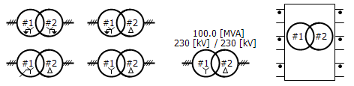
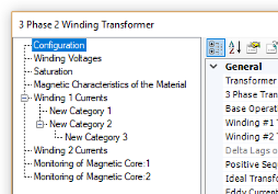
3/5-Limb, Duality-Based Transformers:
Three new components in total: This component rRepresents ing a mode of a 3-phase, 2-winding transformer, a 3-phase, 3-winding transformer, and 3-phase, 4-winding transformer, based on the principle of duality. It They can be used to model a multi-limb transformer or a bank of single-phase transformers. Several methods of entering transformer core, nonlinearity parameters are available. Optional stray capacitances are also available.
Hysteresis Reactor:
This component models a hysteresis reactor. It can be connected to a single-phase or 3-phase node.
![]()
New Photo-Voltaic (PV) Source
A newer PV source model (photovoltaic_source2) is added to the master library. Unlike its predecessor, this component can take typical data available in datasheets. The data required by the previous model was not easily available to the user.
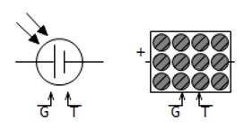
3-Phase Current Source:
This component models a 3-phase, positive-sequence, ideal AC current source.
![]()
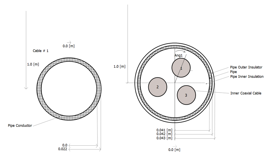
New Pipe-Type Cables
Two new pipe-type cable components have been added to the master library, both based on the existing pipe-type cable: The first is a pipe-only, and the second, a simplified pipe-type component. Both are added to alleviate some headaches in data entry.
Dependent Sources:
PSCAD V5 includes a collection of dependent source component models.
- Current Dependent Current Source:
This component models a single-phase or three-phase scalable current dependent current source.
![]()
- Voltage Dependent Current Source:
This component models a single-phase or three-phase scalable voltage-dependent current source.
![]()
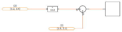
- Voltage Dependent Voltage Source:
This component models a single phase or three-phase scalable voltage dependent voltage source.
![]()
- Ideal Ratio Changer:
This component models a single phase or three-phase scalable ideal ratio changer (i.e. a combination of voltage dependent voltage source and a current dependent current source).

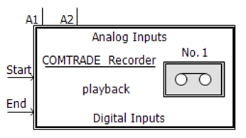
New COMTRADE Recorder Component
The old RTP/COMTRADE Recorder component has been replaced by a new, COMTRADE only component in the master library. All references and functionality to the Real Time Playback (RTP) product, and COMTRADE 91 formats have been removed. Only COMTRADE 99 formatted output is supported.
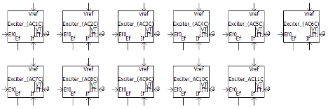
IEEE Standard 421.5-2016 AC Exciters:
The collection of AC Exciters in the master library have been updated from the previous 1992, to the revised 2016 IEEE standard. Includes AC1C, AC2C, AC3C, AC4C, AC5C, AC6C, AC7C, AC8C, AC9C, AC10C and AC11C models.
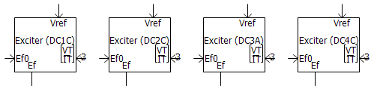
IEEE Standard 421.5-2016 DC Exciters:
The collection of DC Exciters in the master library have been updated from the previous 1992, to the revised 2016 IEEE standard. Includes DC1C, DC2C, DC3A and DC4C models.
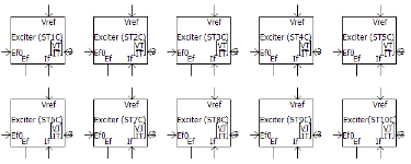
IEEE Standard 421.5-2016 Static Exciters:
The collection of Static Exciters in the master library have been updated from the previous 1992, to the revised 2016 IEEE standard. Includes ST1C, ST2C, ST3C, ST4C, ST5C, ST6C, ST7C, ST8C, ST9C and ST10C models.
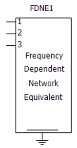
FDNE Component Upgraded to Use Optimized Matrix Storage
A new version of the FDNE component definition called ‘fdne2’ has been added to the master library (the original ‘fdne’ definition is now deprecated). The new version includes an optimized storage matrix.
Individually Configurable, Delta-Connected Load:
This component models a delta-connected load. Each branch can be individually selected to be any series combination of R, L and C elements, or as an open branch.
![]()
Individually Configurable, Delta-Connected, 3-Branch Load:
This component models a delta-connected load. Each leg is a combination of two, parallel branches in series with another branch. Each branch can be individually selected to be any series combination of R, L and C elements, or as an open or shorted branch.
![]()
Individually Configurable, Y-Connected Load:
This component models a Y-connected load. Each branch can be individually selected to be any series combination of R, L and C elements, or as an open or shorted branch.
Individually Configurable, Y-Connected, 3-Branch Load:
This component models a Y-connected load with a neutral connection. Each leg is a combination of two, parallel branches in series with another branch. Each branch can be individually selected to be any series combination of R, L and C elements, or as an open or shorted branch.
![]()
Per-Unit Impedance Branch:
This component models a 3-phase passive branch of R, L and C elements. Parameters are entered as per-unit impedances, based on specified base values.
![]()
Isolation Switch:
This component models an isolation switch for electric circuits. The status of the switch can not be changed during the run. The switch is modelled as an infinite or zero impedance branch.
![]()
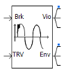
TRV Envelope Generator:
This component generates standardized Transient Recovery Voltage (TRV) curves and outputs violations when the input voltage exceeds the envelope. This is a simplified approach to determining whether a breaker will restrike after a current interruption.
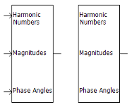
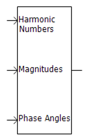
Harmonic Signal Generator:
This component generates a signal composed of user-defined harmonics of varying magnitudes and phases. Harmonic numbers and associated peak magnitudes and phases can be input through ports as an array signal. Alternatively, the user can specify them from a file.
Pick-Up, Drop-Out Timer:
This component models a pick-up, drop-out timer.
![]()
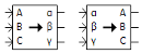
Clark/Inverse Clark Transform:
This component performs Clarke or Inverse Clarke transformation.
Change Detector:
This component detects changes in the input. The output is 1 if a change is detected, otherwise it is 0.
![]()
Dead-Band Controller:
This component models a dead-band controller.
![]()
Scale Changer:
This component does a linear transformation of the input signal in y = mx + c form.
![]()
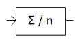
Moving Average Filter
A new component definition called moving average has been added to the v5.1 master library. Given a defined moving window and number of samples within it, this component takes a moving average of its input signal.
Discretizer:
This component discretizes the input signal, from a specified range to a different discretized range.
![]()
Sort Indexer:
This component examines an input data array and outputs the sorted indices of the array in ascending or descending order.
Complex Conjugate:
This component outputs a complex conjugate signal, based on the input, complex signal.
![]()
Electrical Phase Tap:
This component may be used to tap off a single phase, from a multi-phase electrical wire.
![]()
Backlash:
This component models a backlash controller.
![]()
Complex Constant:
This component is used to create a constant, COMPLEX data signal.
![]()
General Master Library Model Enhancements
Complex Signal Support
Most of the standard controls components (CSMF) have been updated to support the new complex signal type in PSCAD V5.
Array Signal Support
Most of the standard controls components (CSMF) have been updated to support array signal (vector) input and output. All components are by default scalar. To utilize array signal functionality, simply modify the component dimension parameter.
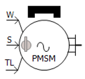
New Data Entry Format for the Permanent Magnet Machine
The PMSM now includes two different data input formats: Equivalent Circuit and Dynamic Model. Equivalent Circuit format represents the electrical characteristics of the machine using parameters like resistance (R) and reactance (X). Dynamic Model format describes the time-varying behavior of the machine, including key aspects such as transient time constants and transient reactance.
Multiple Run Additional Recording Statistical Summary
The ability to add a statistical summary to the output file has been added to the Multiple Run Additional Recording component.
IEC Standard Input Added to the Harmonics with Different Magnitudes Component
The IEC Standard has been incorporated into the input format for the 'harmdiffmag' component. Specifically, the format follows IEC Standard 61400-21-3, specifically Tables 1 and 2 on Page 23.
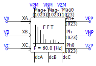
FFT Enhancements
The Fast Fourier transform component now provides support for output signals up to 1023 harmonics. A new input parameter has been added to allow enable/disable control of frequency tracking using a signal variable.
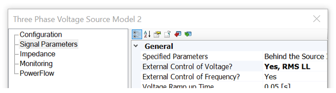
RMS Option for External Control of Voltage Source
External voltage control in this component may now be accomplished via a line-to-line RMS signal, in addition to the existing line-to-ground peak format.
#COSIM Directive in Co-Simulation Component
A new directive has been added to the co-simulation component to act as an alternative identifier to the component definition name. This allows users to create and use their own, custom co-simulation components.
#COSIM $client_id $channel_id $s_dim $r_dim
Where:
1. Client ID: The ID of the application, with which it will be co-simulating.
2. Channel ID: The ID of the channel in the application.
3. Send Size: The size of the data that this component will send to the other application in terms of total of real numbers.
4. Receive Size: The size of the data that this component will receive from the other application in terms of number of real numbers.
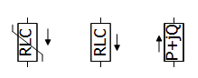
Current Measurement Added to RLC Branch Components
Components var_impedance, rtcbranch and fixed_load1 are modified to provide current measurement through the branch as an internal output. The graphics of each component was also updated to show the direction of current measurement.
Default Capacitive Branch Behaviour in Variable Impedance
The var_impedance component has been modified to give the user a choice on how to treat zero capacitance as a short-circuit or an open-circuit. It is defaulted to a short-circuit to provide backwards compatibility with PSCAD v5.0.

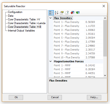
B-H Core Characteristic for Saturable Reactor
The Saturable reactor core characteristic can now be represented as a B-H curve, where data is entered Flux Density (T) vs. MMF (A/m).
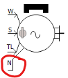
Permanent Magnet Machine Neutral Connection
The Permanent Magnet (PM) machine component has been provided with an external connection to the neutral point of the stator windings.
Mutually Coupled Three Wires – Zero Impedance
The Mutually Coupled, Three Wires component has been updated to provide the ability to model a zero-impedance transmission line. This is helpful when importing models from powerflow software.
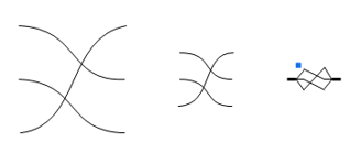
Twist Component Compact View
The new Twist component now has a compact view that matches with compact breakout, as well as a single line view. An additional option is also provided to break the nodes into two, distinct sets by inserting an ammeter between them. This would be helpful when both ends are connected to breakout components.
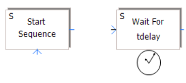
Sequencer Start and Wait Components Now Edge Triggered
The Sequencer Start and Sequencer Wait master library components have been modified to function on and edge trigger, rather than a level trigger. This was done to resolve a sequencing issue that could occur under the right conditions.
Greek and Math Symbols Displayed in EMTDC Constant Tag
PSCAD V5 supports Unicode, so the graphics in the emtconst master library component have been updated to display actual Greek characters and math symbols, instead of spelling them out.
![]()
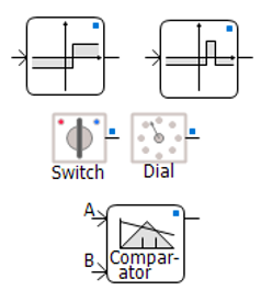
Graphical Display Indicates Conversion of Output to Nearest Integer
Some components in the master library (ex. compar, compare, range, var_pot, var_switch, etc.) have the option to convert the output to the nearest integer. Now, a graphical indicator (a small blue box) when this option is applied.
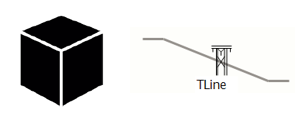
Blackbox Upgrade
The blackbox module feature, first available in PSCAD v4.5 and v4.6, has been updated in V5 to include many new enhancements, including the support of electric networks in combination with control systems.
-
Electric Networks Support: Starting from the top-level page module, an entire electric network, which may span across several module levels, can be collapsed into a single component, complete with multi-instance compatible, Fortran source code. The new component definition includes prefabricated graphical port arrays to represent the network, as well as pre-scripted Branch, Transformers and Matrix-Fill segments.
- Transmission Line and Cable Support: Overhead transmission lines and underground cables are now supported when blackboxing modules. Utilizing a brand-new definition script segment called Subsystems, users may include transmission systems within a module to be blackboxed, provided both ends of each line exist within the same module. The presence of transmission lines also means that multiple, electrical subsystems are now supported for the first time, within non-module components.
-
Global Substitutions: If project-based global substitutions are used within a module hierarchy that is to be blackboxed, the user has two options on how to process them: The default option is to embed (hard-code) the literal value of the global substitution upon creation of the blackbox component. These values will thereafter remain constant and unchangeable. A second option allows users to make each global substitution available as a constant input parameter in the final blackbox component. Each parameter created is unique according to: 1) the actual substitution, and 2) the target unit of the parameter it is used in. For example, if a global called FREQ is used in two parameters, one whose target unit is [Hz] and the other [rad/s], two separate parameters are created.
- Co-Simulation Component: Any Co-Simulation component that may exist in the module being blackboxed, is now fully supported.
- Options: Blackbox-related application options are now presented as a pop-up dialog at each blackbox operation. The options presented each time are read from those set within Application Options | Blackbox category.
-
Retention of Inner Definitions: When blackboxing a page module hierarchy (a module with other modules inside it), it is now possible to retain the blackboxed component definitions of each, individual module, as opposed to keeping just the top-level component definition. If retained, each definition is itself a blackboxed component and may be utilized exclusively from all the others.
C-Coder
PSCAD may now be used to generate a fully formed, ANSI-standard, C language program, which may be run independently of EMTDC. The resulting code can then be used to program micro-controllers, etc.
C-language program generation is accomplished by constructing a control circuit using a collection of our more basic, master library components, specifically from the Control System Modeling Functions (CSMF) section. Once constructed inside of an encapsulating page module, the C-language program is generated with a single click.
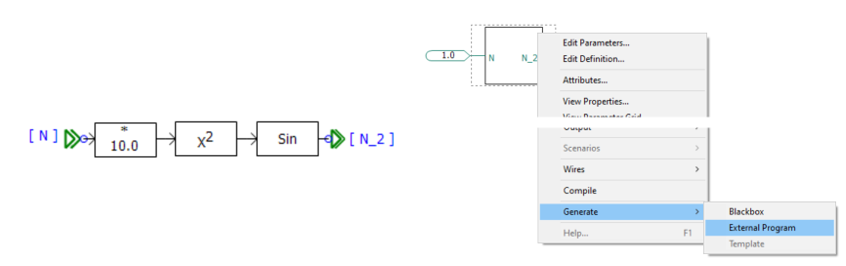
To facilitate this functionality, we have added a brand-new component definition script segment, called ‘C’, where we have placed C-code script that is functionally equivalent to the component’s original Fortran-based script. The ‘C’ component script segment is only ever considered when generating a C-language program.
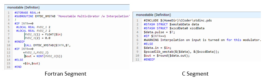
Page Module Creation from a Selection
Users may now collapse any selection of schematic components directly into a page module. Simply select one or more components, using any of the available selection methods, right-click and select Generate | Module. The algorithm will consider both hard-wired and wireless signals that cross the selection boundary. Wireless signals include both those from data and node labels from/to output/input parameters, as well as #OUTPUT directive signals, generated within components, that are passed out via text parameters. If necessary, new parameters will be added to the generated module component to accommodate any wireless signals. All in all, the module component should be run ready once generated.
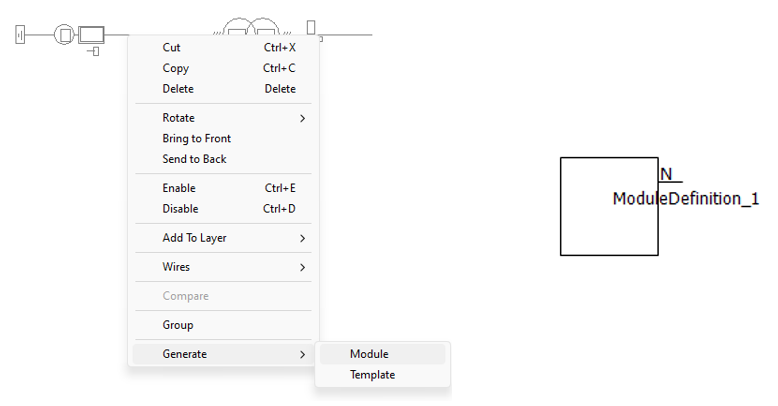
New and Improved External Resource File Handling
The addition of external source (*.f, *.c) and linking of compiled object and library (*.obj, *.lib) files to a project build has, since PSCAD V3, been accomplished via two separate input fields in the project settings, or via the File Reference component. In V5, this functionality has been overhauled and organized into a convenient and intuitive, central area called the Resources Branch.
Appearing as a sub-branch of every project in the workspace projects list, the resources branch provides a means to easily manage all resource files related to a specific project. The resources branch encapsulates the functionality of both the prior project settings fields, and the file reference component, enabling users to append all types of files related to the project; such as Microsoft Word or Excel files, images, Python files for automated scripting, as well any type of text file. All this in addition to the source and linked compiled files supported in previous versions.
The operating system file association settings are utilized so that the proper application is launched when the file is viewed. Also, resource branch icon graphics will display the current status of the resource file, such as whether or not it is included in the build.
Note that the File Reference component will continue to be supported in V5.
A new Application Option has also been added to the Environment category called Relative Path resolution, which provides a means to specify folders where the compiler should look for dependent files. In this way, only the file name need be specified in the project, as long as the file resides in one of the specified folders.
New Binary EMTDC Output File Format
A brand new EMTDC output file format (*.psout) is included with the PSCAD V5 release. A proprietary design, this new format is binary, which ensures a much smaller storage footprint, as well as faster data access. Not only does it store all simulation curve and trace data, but it can also store all sequential or parallel multiple run data, as well as animated graphics information, all in a single file. For example, if you were to launch a volley of 100, parallel simulations, all EMTDC output data is stored in a single file named <project_name>.psout.
Given that binary files cannot be read using a simple text editor, a new utility, called the PSOUT Reader, is also included with PSCAD V5. This utility provides a convenient, tree-based data display environment, and includes appropriate file manipulation features, including the ability to export to the older EMTDC *.inf/*.out file format. The utility may be launched from the Tools tab of the ribbon control bar.
In addition, *.psout files from previous runs, may be added as a resource in the project it was originally run. When invoked, users can display the previously run data on the graphs within that project.
Co-Simulation Interface
A general Application Programming Interface (API) is provided with PSCAD V5, enabling EMTDC to link to, and co-simulate with, just about any external application. Referred to as the Co-Simulation API, it is in its basic form, a C-language structure called EmtdcCosimulation_Channel, which houses a collection c-functions. These functions can be used to customize an interface on the external application-side. At the same time, a new master library component called Cosimulation, may be utilized in a case project to quickly provide the PSCAD/EMTDC side of the interface.

Note that the onus remains on the user to program the interface from the external application side, as all external applications differ in complexity and purpose. A complete description of the Co-Simulation API can be found in the PSCAD Application Help.
Rubber Banding (Sticky Wires)
A new, tri-segment ‘sticky’ wire component has been added to PSCAD V5. When either endpoint of this wire is attached to another object (component, bus or another wire), the wire’s endpoint will ‘stick’ to the object. If the object is moved, the wire endpoint will remain ‘stuck’, and the sticky wire will stretch (like a rubber band), as the object to which it is attached is moved around.
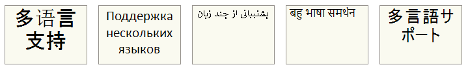
Multiple Language Support in Sticky Notes (Unicode)
The PSCAD V5 codebase has been updated to fully support Unicode, which enables users to use all known writing systems within sticky notes. This of course includes the Cyrillic alphabet, Chinese characters, etc. This is a very important new feature, which has been passionately requested by many of our Asian users.
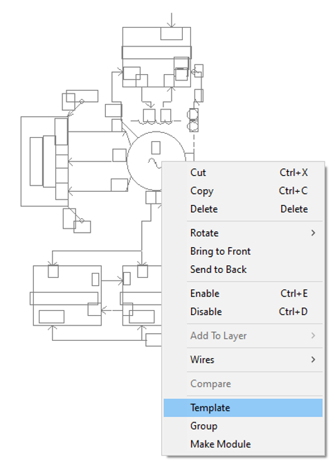
Component Templates
Pre-configured collections of components and modules may now be consolidated and stored as a Template object. Functional in both library (*.pslx) and case (*.pscx) projects, simply select a group of components on the schematic canvas, right-click and select Template.
Once templated, the pre-configured group of components are stored in the project under the Templates branch in the workspace tree:
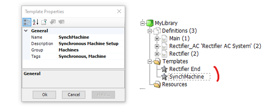
Once created, the template becomes viewable and searchable (according to its name and given Tags) via the Component Library Viewing pane. An instance of the template can be created either from the Component Library Viewing pane, or directly from the workspace tree.
Circuit Building Enhancements
We have added several new features that will help to make user’s circuit-building experience more enjoyable:
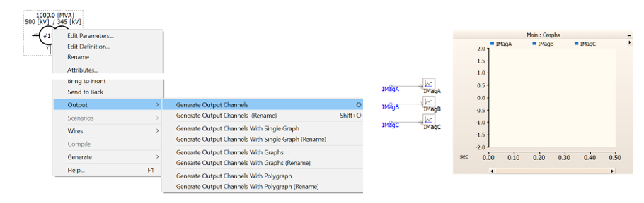
- Automatic Output Channel Creation: A component context menu option has been added that will scan the component for output parameter signals, and the automatically construct an output channel with a data label attached, with names pre-set to the output parameter name. In addition, users may take this one step further by automatically creating and adding these output channels to a graph, or a meter in a control panel.
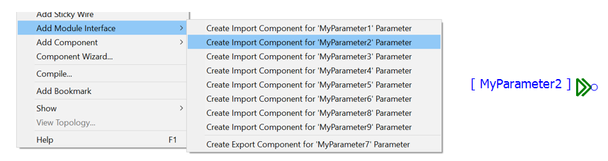
- Add Module Interface: A new schematic canvas menu function allows you to quickly add XNodes or import/export tag components to a module canvas, based on any module port or parameter that has not already been paired with one of these components. The component is added pre-named to match the chosen parameter or port name.
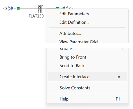
- Auto T-Line/Cable Interface: A new transmission line/cable context menu function allows you to quickly generate a preconfigured, interface component to correspond with any transmission segment properties component. Simply right-click on the transmission segment properties component and select Create Interface.
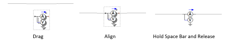
- Component Wire Insertion: A new mechanism has been added to allow users to automatically insert a component inline within a wire, without going through the cumbersome steps of breaking the wire apart. Simply move the component atop a wire, lining up the connection ports, hold down the space bar and release the mouse button.
Cluster Launch System (CLS)
The utilization of high-performance and parallel processing functionalities requires multiple processor cores – the number of which may exceed those available locally on a typical workstation. In such situations, users may either purchase a large and expensive, high-performance computer (ex. 64-core) or connect a collection of multi-core computers across a Local Area Network (LAN). The latter option is referred to as a computational cluster.
.png)
Running processes across multiple computers requires additional software to manage the simulation processes. Enter the Cluster Launch System (CLS), a utility that can both launch and manage simulations on a computational cluster.
For example, a user wanting to run 10 simulations on a computer (Host 1) comprising of 4 cores, can use the CLS to configure a computational cluster and run 10 simulations using several multi-core computers connected across a LAN. As shown in the figure above, Host 1 can be treated as the master, since PSCAD is running on this computer. PSCAD launches the CLS, which is then used to configure a computational cluster comprising of Host 1, Host 2 and Host 3.
Tandem Lines: Sliding Faults
With PSCAD V5, we introduce tandem line configuration (or Tandem Lines) for both underground cable and overhead transmission segments. This in response to numerous requests for an easier way to automate a sliding-fault style study. The tandem lines feature combines multiple run control, parallel-processing and the transmission segment configuration components, to enable quick and efficient sliding-fault simulations.
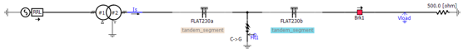
Using the basic, standalone multiple run control configured in the project settings Runtime tab, a tandem line simulation involves a pre-solve of all possible transmission segment lengths (i.e. produces multiple *.tlo files, based on the tandem segment parameters) prior to launch. Then the simulation is run multiple times, each time using different segment lengths, creating the illusion of a sliding fault.
Mixing of Overhead and Underground Transmission Systems
The underground cable transmission segment editor and line constants program (LCP) have been modified to allow the combination of overhead transmission tower and underground cable cross-sections, within the same right-of-way.
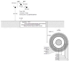
The additional formula in the LCP takes care of the mutual impedance between aerial and underground lines.
COMPLEX Signal Type
Complex-type signal variables, in addition to Real, Integer and Logical-types, are now supported in PSCAD V5. Support for #LOCAL-type, complex declarations in component definition script was introduced in v4.6 but did not include the creation and support of actual complex-type data signals. V5 includes the following enhancements to provide full support:
-
A Complex data type option in component graphics port objects.
-
A Complex parameter-type for both module and non-module components.
-
Miscellaneous new and updated master library components, including a Complex constant tag. Also Complex signal support in many CSMF components.
-
New orange colour represents Complex signal wires.
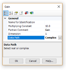
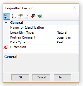
Enhanced Component Parameter Dialog
In an effort to provide a more efficient means of organizing very large amounts of component input and output parameter data, the component parameter dialog has been greatly improved for the V5 release. Two huge improvements were made: The manner in which parameter category pages are organized, as well as the inclusion of a Java-based, dynamic display and feedback window, called the Dynamic Help Pane.
The flat, drop-list category page format, which has been a part of PSCAD since the V2 days of the 1990s, has been replaced by a multi-level, tree-based category window. The new tree style can be extended to provide multiple branch levels (branches within branches), to provide a second dimension to the organization of categories.
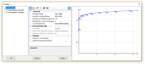
A very powerful and customizable display window, called the Dynamic Help Pane, is also included in the new parameter dialog. The new pane is simply a viewing mechanism to display the output of an associated, JavaScript-powered, HTML file. The power and flexibility of JavaScript and its libraries may be utilized to create a wide assortment of parameter data visualizations, from help text, to images and dynamic graphs that change as the data changes.
For example, the arrestor component in the master library has associated with an HTML file that defines a V-I curve plot, based on the V and I parameter data entered in the dialog. The curve is displayed in the side panel window as shown below. The graph is dynamic and will change immediately if the parameter data is changed.
Project Navigation Enhancements
Multiple enhancements have been included with PSCAD V5, to help users navigate projects quicker and more efficiently, as well as minimizing the risk of getting lost in larger projects. Prior to V5, project navigation was performed by drilling down through multiple module layers manually. Navigating upwards was accomplished in the same way. PSCAD V3 and V4 provided a sub-tree under each project, containing a clickable representation of the existing module hierarchy, allowing users to jump to specific modules. In X4 (v4.3 to v4.6), this navigation tree was brought out into its own area, referred to as the workspace secondary window.
V5 now boasts a handful of other navigation-related niceties, in addition to the navigation tree, as described in the following bullets:
-
Navigation Bar: Each and every schematic canvas tabbed viewing pane, possesses its own navigation bar. The bar shows the hierarchal path, including each navigation level, to the present viewing position. Each level itself is a navigable link, and displays the module definition name and instance number. Users may easily traverse up the path with a simple click of the mouse.

-
Bookmark Component: Bookmarks are essentially a special type of a component that provides a clickable hyperlink to a xy-coordinate on a specific schematic canvas within a project. Bookmarked points are first defined, and then a bookmark component can be added from the ribbon bar that, when clicked, will navigate to that exact position from anywhere in the project.

-
Bookmarks are also managed from within the Bookmarks pane. This pane provides a convenient and navigable list of bookmarks.
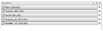
-
Case Link Component: Case links are a special type of component with a single purpose: When clicked, they will open a project from anywhere on your local system, into the current workspace. Simply add a path to the project file and give it a name.

-
Hyperlink Component: Hyperlinks are special components that may be used to set a URL to a specific webpage, for easy access to information related to the current study, for example. Simply add a URL to the project file and give it a name.

More Powerful Parallel Multiple Run (PMR)
In computing, the acronym SPMD (or 'spim-D') stands for Single Program, Multiple Data, and is one of several computer architectures described in a classification called Flynn's taxonomy. It is a technique used to achieve data parallelism, where multiple instances of a simulation are run simultaneously on multiple processor cores, given different input, in order to obtain overall results quicker and more efficiently than if running them sequentially. In PSCAD, the SPMD technique is referred to more affectionately as a Parallel Multiple Run (PMR).
The PMR feature enables users to launch multiple simulation runs in parallel, based on a single case project, but providing different data to each parallel simulation task. Each simulation is run independently on its own, unique processor core.
.png)
Multiple Plotted Data Sets: If the user chooses to enable tracing (passing plot data back to PSCAD for viewing) on all parallel tasks, a convenient list of data sets will appear under the simulation. These sets will represent each individual run, and when clicked, will display the data for that run in the project graphs. For example, if the tracing is enabled for all parallel tasks in the above simulation, all 49 runs will appear as follows:
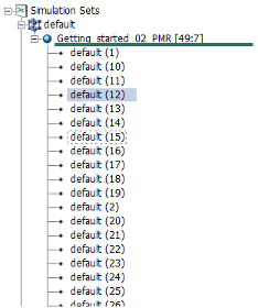
The simulation task with rank 12 is currently selected, so this data will be displayed in the project graphs.
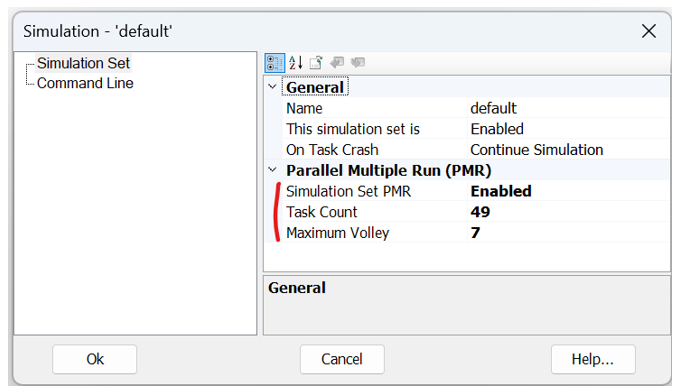
Combined PMR and PNI Simulations: Those who utilize the High-Performance Computing (HPC) functionalities in PSCAD, rejoice! It is possible to simultaneously run a PMR of a Parallel Network Interface (PNI) simulation. Setup of such a simulation is straightforward: Simply provide Task Count and Maximum Volley parameters to the Simulation Set encapsulating the PNI simulation:
Simulation Set Functionality Improvements
Simulation sets were introduced in PSCAD v4.5 in order to facilitate the launching of parallel simulations. They have been continuously enhanced in each version since, and V5 is no exception:
-
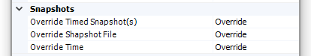
Project Settings Override: The ability to override runtime project settings, in each simulation task, is now included.
-
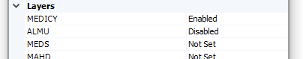
Layer Settings Override: If a project contains layers, individual settings may be overridden on a per-simulation task basis. This feature provides a lot of flexibility, as project schematics can be modified between simulation set runs.
-
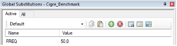
Global Substitutions Set Select: In PSCAD V5, it is possible to maintain multiple sets of global substitutions for each project. A single global set may now be associated with a simulations task, allowing users to modify global substitution values between simulation set runs.
-
Enable/Disable Set: Use the enable/disable simulation set option to enable or disable individual simulation sets. Disabling a set will ensure it is not included when running all sets.
-
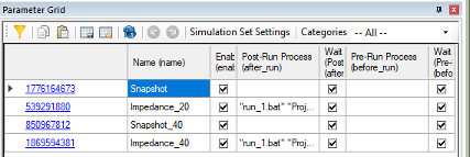
Parameter Grid Support: Use the parameter grid to manipulate the options of multiple simulation sets simultaneously.
-
Force Re-Build: The ability to force a re-build of the project, prior to launching the simulation, is now available as a Simulation Task option. When enabled, this setting will also ensure that the temporary folder is cleared between runs.
-
New Parallel Run Options: New options, such as Maximum Volley (limits the number parallel tasks launched on a volley), and Snapshot File (allows the selection of specific snapshot files based on rank number), have been added.
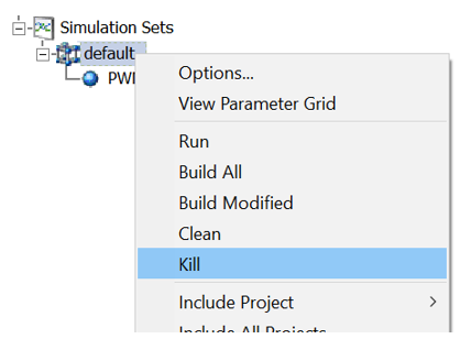
- Easy Kill of Launched Simulation Processes: If PSCAD crashes during a large simulation, or is unable to stop all running simulation processes, it can be difficult to track these down and kill them manually. A kill option has been added the to simulation set, which will find all simulation processes pertaining to that set by name and kill them. This will be done regardless of whether they were started by the current instance of PSCAD or not.
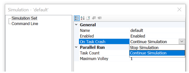
- Option to Automatically End Simulation Set on Task Crash: If a single EMTDC instance crashes or dies during a simulation set run, that simulation set will become stuck, continuously waiting for the dead task. This could put an exceedingly large amount of stress on a machine until the task is manually killed. No longer. We have added a simulation set option that will automatically shut down the entire set, if one or more tasks crash or die.
New and Enhanced Global Substitutions Design
The global substitutions feature, part of the PSCAD X4 family of products (v4.3 to v4.6), has been completely redesigned for V5. Based on feedback from users over several years, we have assembled an entirely new global substitutions functionality, much more flexible and intuitive than the previous design. Major changes include:
-
A new global substitutions pane, which provides a central area to edit, add and delete all global substitutions related to a single project.
-
Inclusion of alternate global substitution values (or sets of values) when running the project as a task, in the context of one or more simulation sets.
-
Store, append and replace global substitutions to/from file in *.cvs format.
-
Set the min/max limits of slider components.
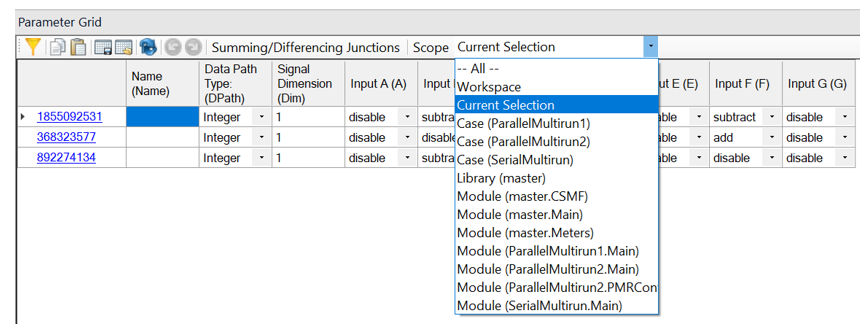
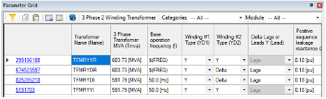
New and Improved Parameter Grid
The immensely popular parameter grid feature has been completely re-architected in PSCAD V5, specifically to address the user-identified shortcomings of its predecessor in v4.6. For the most part, the new parameter grid looks and feels like the old one. However, under the hood, we have made many changes that will facilitate functionality that was missing previously. Here is a list of some of the more significant enhancements:
-
Support for buses, transmission lines, simulation sets, file reference components and sticky notes: Virtually all schematic objects.
-
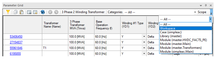
Results may be filtered by parameter category page, project type, specific page module, or even component selectionin addition to page module. It is also possible to include results from the entire workspace.
-
Disabled parameters (instance-based) are now displayed as such in the parameter grid results.
-
Store, append and replace parameter grid results to/from file in *.cvs format.
-
Parameter grid results may be transferred directly to a spreadsheet, modified and then transferred back via copy/paste.
-
Full undo/redo support.
We have also expanded the parameter grid presence and support into many areas throughout the application:
- The parameter grid goes workspace wide! Users may set the scope of results across the entire workspace, to include results from all modules in all loaded projects.
- Project settings.
- Canvas settings.
- Component graphics canvas.
Previous Run Playback
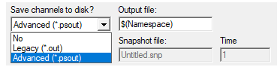
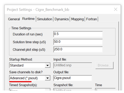
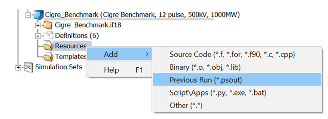
Previous Run Playback enables a replay of a previously run simulation, where the output results have been written in *.psout format (i.e. Save Channels to Disk? Is set to Advanced (*.psout)).
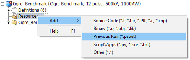
Once the simulation is complete, simply add the resulting *.psout file as a Previous Run project resource:
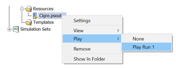
Once added, right-click again and select Play and then the run stored within the *.psout file you would like to play back:
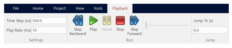
The playback speed is adjustable. The graphs, controls, instruments, and animations will be re-displayed during the playback. The ribbon control bar will automatically display a Playback tab, which provides an assortment of controls:
Previous Run Playback is useful for doing presentations where performing the simulation may take a long time or perhaps the simulation is too fast for in-simulation analysis.
Component Library Viewing Pane
A new viewing pane has been added that provides a searchable environment for finding and viewing available component models, across the entire workspace.
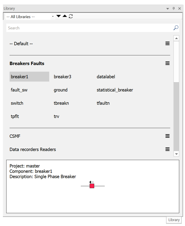
Filters provide the ability to focus the view on a specific project, or across all loaded projects in the workspace. Fully searchable, users can quickly find what they are looking for and add an instance of the component to the schematic with a single click. A viewing window at the bottom of the pane provides information about the component, including its graphical appearance.
Smart Paste
Cut/copy and paste just got a whole lot smarter in PSCAD V5. Now when an object is copied, PSCAD stores a great deal more information on the Windows clipboard, so that when it comes time to paste, an intelligent decision can be made, depending on the context of where the object is being pasted. This can save click steps in many areas:
-
Copy/Paste of Output Channels: Copy an output channel component. Depending on where it is pasted, PSCAD will intelligently perform the correct operation: Paste over a graph, and a curve will be created; paste on the schematic canvas to copy the component; paste over a blank graph panel and a new graph containing a new curve will be created; paste over a control panel to create a new meter interface.
-
Paste External, Copied Text Directly as Sticky Note: Text copied from an external file, such as Microsoft Notepad or Word, is now formed directly as a sticky note when pasted on the schematic canvas.
-
Multi-Select Copy Transfer: Select a single module or multiple modules and select copy. Paste transfer into the same project or a new project.
-
Layer Information Included in Copy/Paste: All layer information is now included when a component is copied. On paste, the layer state will be maintained. If the layer exists already, the component is added to it; if not, a new layer is created.
-
Paste Rename: When a component that contains a text input parameter with symbol name Name is copied, this text can now be given a new name, based on the original seed text. For example, a component with a Name parameter with value MyComponent can be automatically renamed to MyComponent_1. This is especially useful when copying data labels, node labels and xnodes. To make use of paste rename, right-click and select Paste | Paste Rename on paste of a copied component.
-
High-Resolution Bitmaps: Copying of schematic canvas components now produces a high-resolution bitmap image, which when pasted into other applications, maintains high image quality.
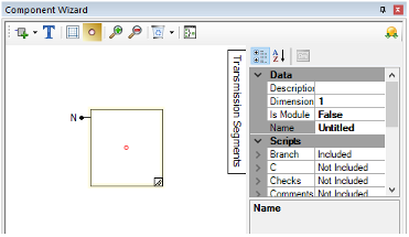
Enhanced Component Wizard Design
The component wizard has gone through a few changes over the years. The original design, which survived through PSCAD V3, V4 and on through to X4 (v4.3), was redesigned for the v4.4 release, and then again in v4.6.
PSCAD V5 includes a completely new and refactored component wizard, our best and most powerful iteration yet. Unlike its predecessors, the V5 component wizard provides a much higher level of flexibility, including the following user-requested enhancements:
-
Fully sizeable box graphic.
-
Flexible port connection placement: Once a port is added, it can be moved around the box graphic to the desired position.
-
Quick access property view.
-
All component definition script segments may be optionally added at the time of creation.
-
Automatic creation of a dummy language interface to either FORTRAN, C or MATLAB, upon creation of the Fortran, Dsdyn and/or Dsout segments.
Animated Graphics Patch
The animated graphics feature has been in use since PSCAD V3, and has remained mostly unchanged, until now. Prior to V5, the animated graphics display (ex. breaker state colour, multi-meter PQ text, etc.) would only update if the corresponding component was currently in view, during a simulation. This means that if the user was to navigate to another page module schematic after the run had finished, the graphical state of any components in that schematic may not be up to date. For example, if a breaker went from open to closed while not in view, it may still appear green if the user navigates into its page module following the end of run.
This issue has been rectified in V5, so that all animated graphics will show their last state in the simulation, regardless of whether they were viewed or not.


